GrassFlap.com Phone: (502)594-3546 9
SE Pedal Location & Cable Routing
Option 1
Option 2
Option 3
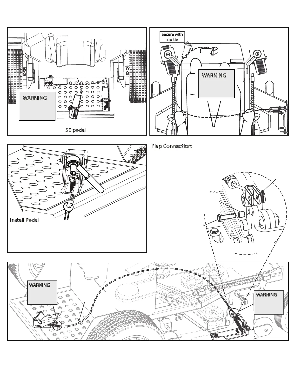
Preferred locations for SE pedal assembly.
WARNING:
First
½” after
tting must
be straight
SE Pedal Cable Routing
on Stand-On
Tie cable
down
WARNING:
First ½” after
tting must
be straight
WARNING
:
First ½” after
tting must
be straight
2x
Install Pedal
A) Mark and drill two 11/32” holes, if needed, for pedal
mounting bolts.
B) Tighten two 5/16” x 1” carriage bolts to secure pedal
assembly to mower deck.
Option 1
Secure with
zip-tie
Option 2
SE Pedal Cable Routing
on Zero Turn
WARNING:
First
½” after
tting must
be straight
A
B
C
D
FLAP CONNECTION
3/16”
Clevis Pin
10-99-22
Bushing Cable
Pin Flap End
10-99-28
Flap Connection:
A) Place 1/4” bushing in ap.
B) Slip clevis onto ap.
C) Insert 3/16 pin with head
on spring side.
D) Insert cotter pin and bend
around pin.
Cotter Pin
 Loading...