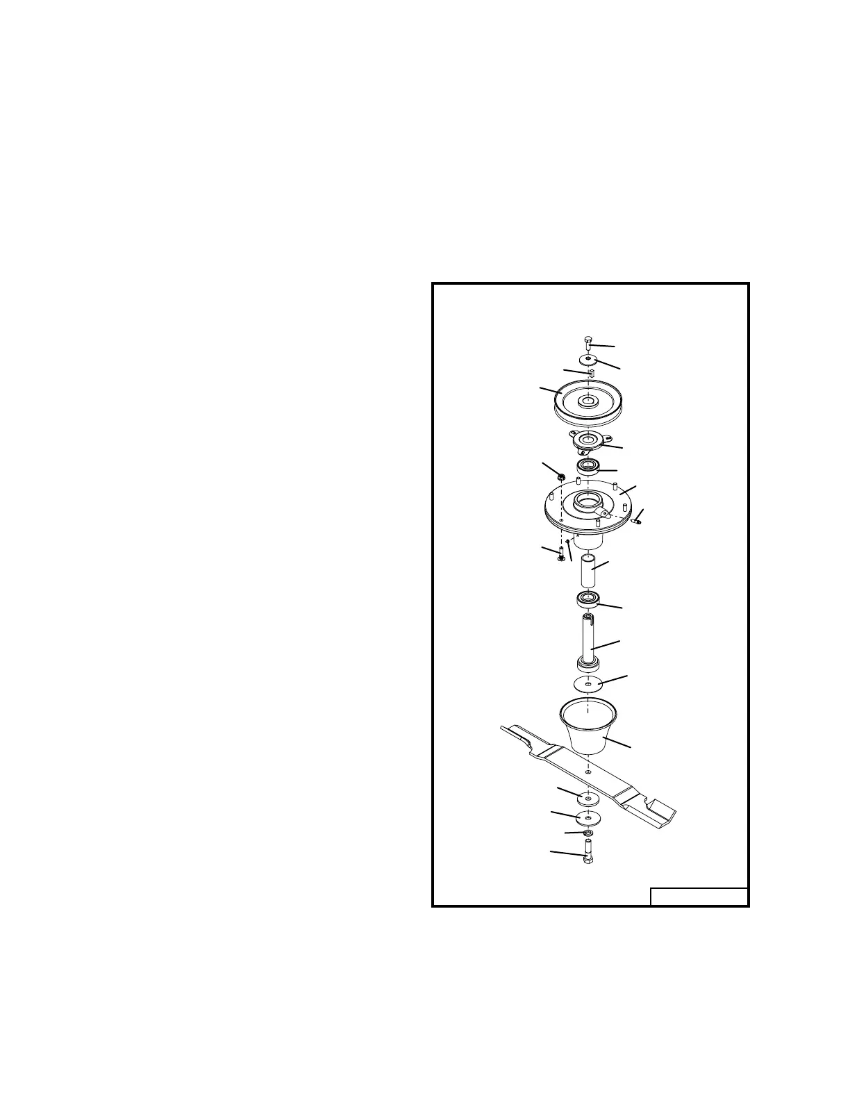
Fig. 24
GEARBOX REMOVAL
(Refer to illustration page 29 and 31)
1. Remove deck from tractor.
2. Remove belt shield and belt.
3. Remove half shaft assembly from gearbox.
4. Remove the gearbox mounting bolts.
5. Remove bolt and cupped washer on sheave and
remove sheave from gearbox. A wheel puller
may be required.
6. Lift out gearbox and repair or replace.
Reverse removal procedure to reinstall gearbox.
BLADE SPINDLE ASSEMBLY
REMOVAL
1. Remove belt shields.
2. Remove belt.
3. Remove blade.
4. Remove spindle assembly from mower by
removing the six nuts that attach the spindle
housing to the mower deck.
BLADE SPINDLE REPAIR
(refer to Fig. 24)
Mark sheave on top side so it will not be in-
stalled upside down on reassembly.
Remove top bolt from spindle sheave and re-
move sheave with a wheel puller. Make notes if
you remove any spacers or washers not shown in
illustration, as they will need to be reinstalled as
they were removed.
Press spindle shaft (item 20) down through spindle
housing (item 7).
With shaft removed, press bearings out of hous-
ing or remove from shaft as necessary.
Inspect parts and reassemble with necessary
new parts.
Install lower bearing (item 6) on shaft (item 20). In-
stall bearing spacer (item 10) on shaft. Install this
assembly into housing. Press top bearing (item 6)
down against bearing spacer. Install square key
(item 22), top bearing shield (item 5), sheave (item
21), cup washer (item 4) and bolt (item 3) in same
sequence as removed. Tighten bolt (item 3) to 50-
55 ft lbs.
Rotate assembly to check free movement, lubri-
cate and install on mower.
26
Rev. 11-07
03083D
19
3
4
22
21
5
6
23
7
8
9
10
6
20
18
13
14
15
16
17



 To Next Page