Do you have a question about the GRAUPNER BO 209 MONSUN and is the answer not in the manual?
This document provides comprehensive instructions for assembling, operating, and maintaining the Graupner BO 209 MONSUN, a radio-controlled model aircraft designed for both internal combustion and electric motors. The model requires a HoTT radio control system with at least five functions and nine servos, with the transmitter capable of servo rotation reversal.
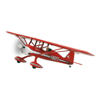
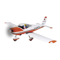
The Graupner BO 209 MONSUN is a highly prefabricated model aircraft, designed for enthusiasts who enjoy building and flying RC models. It supports both internal combustion engines up to 33 cm³ and electric motors, offering flexibility in power plant choice. The model features a wingspan of 2200 mm and a fuselage length of 1660 mm, making it a substantial and realistic replica. The design incorporates control surfaces such as ailerons, elevators, rudder, and landing flaps, all controlled by servos to ensure precise flight maneuvers. The aero-tow mechanism, located just behind the canopy, allows for the model to be towed, adding another dimension to its operational capabilities. The model's undercarriage includes a nose gear and two main wheels, designed for smooth take-offs and landings.
The assembly process begins with familiarizing oneself with all components and construction stages. Control horns for the ailerons, landing flaps, rudder, and elevators are to be sanded and glued into their respective slots. Servos are installed in the wing and tailplane mounts, with their cables extended and secured. It's crucial to set the servos to their middle position using the RC system before installing the servo levers. The servo attachment blocks require screws, rubber grommets, and brass hollow rivets for secure fastening. The hollow rivets can serve as a drilling template for 1.5 mm holes. Servo cables are then pulled through the wing and tailplane halves using a thin string.
The pushrods for the ailerons, landing flaps, and elevators are screwed together, adjusted, and secured against loosening with thread lock fluid and lock nuts. Landing flap hinges are secured with heat-shrink tubing and screwed into marked positions on the underside of the wings, ensuring proper alignment with the trailing edge. The landing flaps are then taped in place and fastened with screws. Transparent covers for the wing tip lights are adjusted and attached with adhesive film. The wing securing bolts are screwed into the wing roots and secured with thread lock fluid.
For the fuselage, boarding steps are glued together and fastened to the wing halves using plywood tabs, allowing for their removal during transport. The vertical stabilizer can be permanently glued or removably fastened with two screws. The tailplane is installed from underneath the fuselage using three Allen screws, tightened just enough to secure it firmly. Pull cables are attached to the rudder control horn and then to the rudder servo, ensuring the rudder is centered when the servo is in its middle position.
The aero-tow mechanism is screwed into place behind the canopy, with thread lock fluid applied. The aluminum part must be shortened to allow free movement of the clevis, and the rods adjusted accordingly. The aero-tow release is best operated by a momentary switch on the joystick, with servo travel adjusted as needed. The nose gear is fixed in its brackets by tightening a screw in the collet, and its pull cables are assembled, ensuring the nose gear is in a neutral position when the servo is centered. The nose wheel and its cover are then installed, requiring a 9 mm hole to be drilled/filed into the left side of the cover.
The nose gear steering servo and rudder servo can be connected to the same receiver socket using a Y-lead or a mixer at the transmitter. The rudder control horn servo is fastened to the fuselage side wall with self-tapping screws. The rudder linkages are prepared and attached, again ensuring the elevator is in a neutral position when the servo is centered. The two main undercarriage components are fastened to the bottom of the fuselage with Allen screws. For the main wheels, a hole is drilled/filed in each cover, and plywood reinforcements are glued inside the covers, aligning the drill holes with the wheel axle. After the glue sets, the axles, wheels, and collets are installed and fastened to the undercarriage, with covers aligned parallel to the ground.
For internal combustion motors, the fuel tank assembly involves slipping plastic tubing onto the clunk pick-up and pushing the free end onto one of the tank stopper tubes. The tubes are heated to bend them easily, with one facing down for filling and the other upward for overflow. The tank stopper is pushed over the throat and tightened with a Philips-head screw to ensure a complete seal, which can be checked by submerging the tank in water and blowing air into it. Fuel tubing lengths are connected to each stub tube, marked for motor, overflow, and filler. The clunk tube connects to the carburettor, the overflow runs downward, and the filler tube can be routed through a drill hole in the engine bonnet and sealed with a plug. The attachment block for the tank is fastened with two screws.
The internal combustion engine, such as the OS MAX GT 33, is installed on the fuselage bulkhead using Allen screws and aluminum bushings. The throttle servo lever is attached to the linkage connector, ensuring free movement. The servo is fastened to the board, and the throttle linkage is attached to the carburettor lever using a double-cranked section. With the carburettor half open and servo in the middle, the pushrod is fixed with a grub screw. The throttle rod is adjusted so the carburettor is half open when the servo is centered, and servo travel is set to stop the engine when the throttle stick and trim are fully back. Choke flap rods are installed, angled to be activated through the engine bonnet opening, avoiding the propeller arc. The silencer is attached to the motor with bolts and a seal. Openings in the engine bonnet are cut or filed for the silencer outlet, spark plug, and cylinder head, ensuring 2 mm clearance between the spinner base plate and the bonnet's front edge. Four attachment points are marked on the bonnet using scrap wood strips with 3 mm holes, which are then taped to the fuselage and fastened with Allen screws. The bonnet is then pushed up under the strips, ensuring 1.5-2 mm clearance, and the attachment points are marked on the bonnet. Finally, the engine bonnet is attached with four Allen screws.
For electric motors, the motor is attached to the bulkhead using the included motor bulkhead, bolts, nuts, cylindrical aluminum bushings, and aluminum pipe sections. The distance between the bulkhead and spinner base plate should match that of the internal combustion engine, requiring four equal-length pieces of aluminum pipe. The motor rests on four stilts, and the hexagonal bolts are cut flush with the nuts. Fastening points are marked on the motor bulkhead, and the electric motor is attached. The speed controller is also fastened to the bulkhead.
The cockpit canopy assembly involves gluing seat backs and a pilot figure in place using double-sided tape. The canopy itself is attached with transparent tape. Navigation lights and decals are fitted and glued, referring to the carton illustrations for correct placement.
Before flying, the model must be balanced. With an empty fuel tank, the model should balance level when supported 100-110 mm aft of the wing's leading edge, ideally in an inverted flight position. The center of gravity can be adjusted by shifting receiver battery positions. Transmitter trims must be centered, and all control surfaces precisely centered in their neutral position. Recommended rudder deflections for normal flying are: ailerons 35 mm up and 15 mm down, elevators 25 mm up and down, rudder 75 mm left and right. For landing flaps, take-off is 15 mm down and landing is 60 mm down. Exponential values of 30% are recommended at the transmitter.
Regular maintenance is crucial for the longevity and safe operation of the BO 209 MONSUN. Before each flight, a pre-flight check is essential. This includes screwing in and extending the transmitter aerial, then switching on the transmitter followed by the receiver. At an appropriate distance, verify that all control surfaces are working correctly and deflecting in the right direction. This check should be repeated with the motor running, with someone securely holding the model. For first-time flyers, it is highly recommended to seek assistance from an experienced person for both the pre-flight check and initial flights.
After each use, the model should be carefully cleaned, including removing any dirt from the propeller. Only suitable cleaning agents should be used for the model and RC components. If the model is to be stored for an extended period, all moving parts must be cleaned and re-lubricated to prevent seizing and ensure smooth operation upon next use.
It is vital to ensure that all rods move freely and through their entire controllable path without mechanical impedance. The radio control system must be checked frequently for wear. Batteries, especially transmitter and receiver batteries, must be fully charged before each take-off. If dry cells are used as a power supply, they must never be recharged. Rechargeable batteries are the only ones that can be recharged. The range of the radio control system must also be checked.
During operation, model motors generate significant heat, so motor and shock absorbers will be very hot. Care must be taken when making adjustments, and protective gloves should be worn to avoid serious burns. After operation, any residual fuel must be removed from the tank and motor. Before every operation, the model and all its attachments, such as propellers, control surface linkages, and rudders, must be carefully checked for damage. Any faults found must be corrected before flying the model again.
The model and RC equipment should be protected from intense humidity, heat, cold, and dirt, especially during transport. All batteries should be removed before transporting and storing the model.
| Category | Toy |
|---|---|
| Length | 1100 mm |
| Weight | 1200 g |
| Material | Balsa and plywood |
| Recommended Battery | 3S LiPo |
| Skill Level | Intermediate |
| Motor | Brushless |