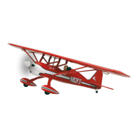
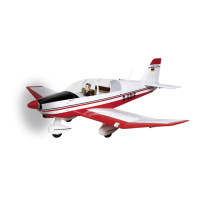
This document serves as an instruction manual for the Graupner STARLET 2400 model aircraft. It provides detailed guidance on assembly, operation, and maintenance, along with crucial safety notes and warnings.
Function Description
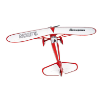
The Graupner STARLET 2400 is a highly pre-fabricated, radio-controlled model aircraft designed for both internal-combustion engines (glowplug or petrol) and electric motors. It requires a four-function radio control system with at least five control functions and ten servos, including a servo reverse facility on the transmitter. The model is intended for recreational flying and is not to be used as a man-carrying machine. Its design emphasizes ease of construction while maintaining high safety standards and robust flight performance.
Important Technical Specifications
- Wingspan: Approx. 2400 mm
- Fuselage length (excl. spinner): Approx. 1540 mm
- Wing area: Approx. 76 dm²
- Tailplane area: Approx. 15 dm²
- Total surface area: Approx. 91 dm²
- All-up weight (according to fittings): Approx. 9600 g
- Longitudinal dihedral: 0 - 0.5 degrees
- Centre of Gravity (CG): Approx. 160 - 170 mm aft of the leading edge (measured at the wing roots adjacent to the cabane). The model should balance level, ideally with the nose angled slightly down, when supported at this point with the fuel tank empty or flight packs in place.
- Control surface travels:
- Ailerons: 25 mm up, 9 mm down
- Elevators: 20 mm up, 20 mm down
- Rudder: 35 mm to right and left
- Recommended Exponential: 30% on all control surfaces.
Recommended Internal-Combustion Engines:
- Glowplug Engine: OS MAX FS 200 S (Order No. 2728)
- Capacity: 32.4 cc
- Silencer: Included
- Propeller: 1318.45.25
- Petrol Engine: GT 33 (Order No. 2772)
- Capacity: 33 cc
- Silencer: Included
- Propellers: 1318.45.25 or 1318.50.25
Recommended Electric Motor System:
- Electric Motor: COMPACT 630 (Order No. 7725)
- Propeller: 55 x 25 cm (Order No. 1326.22x10)
- Flight Battery: LiPo V-MAXX 45C 5/4200 18.5 V/4.2 Ah (Order No. 9740.5) - Two required.
- Speed Controller: COMPACT CONTROL 80 HV (Order No. 7228)
Recommended Radio Control System Components:
- Transmitter: Mx-16 to MC-24 computer systems are particularly recommended.
- Receiver Power Supply: Two GRAUPNER LiFe 2/2900 6.6V JR (Order No. 7672.2).
- ON / OFF Switch: PRX 5A (Order No. 4136).
- Servo Extension Leads:
- For aileron servos to receiver (two needed): Order No. 3935.65.
- For aileron servo leads in wings (two needed): Order No. 3935.50.
- For elevator servos (two needed): Order No. 3935.75.
- Servos: Standard-sized servos with an output torque of around 50 Ncm are suitable.
Adhesives and Fluids:
- Fast-setting epoxy resin: UHU plus schnellfest (Order No. 962)
- Slow-setting epoxy resin: UHU plus endfest 300 (Order No. 950.43)
- White glue: UHU Holzleim express (Order No. 958.60)
- UHU hart: Order No. 534.35
- Cyano-acrylate ("cyano"): Order No. 5821 or 5822
- Thread-lock fluid: UHU schraubensicher (Order No. 952)
Accessories for Operation (not included):
- Fuel: Suitable for the chosen engine (petrol/oil mixture).
- Fuel tubing: E.g., Order No. 1325.2.
- Manual fuel pump: E.g., Order No. 6870.
- Ignition battery: E.g., Order No. 8716.5.
- Battery chargers and charge leads: Refer to the main FS catalogue for electric-powered versions.
- Set of cross-point screwdrivers
- Pointed-nose pliers
- Flat-nose pliers
- Side-cutters
- Balsa knife or razor blade
- Set of twist drills
- Pencil
- Felt-tip pen
- Fine-tip soldering iron
Usage Features
Assembly:
The STARLET 2400 is highly pre-fabricated, making assembly relatively quick. However, careful and accurate work is crucial for the model's strength and flight performance.
- Pre-assembly Check: Before starting, thoroughly read the instructions, check all kit components, and familiarize yourself with the construction procedure.
- Film Covering: Minor creases or bubbles in the film covering can be corrected with warm air and a soft cloth. Warps can be gently twisted in the opposite direction while applying warm air. Avoid excessive heat to prevent melting the film.
- Screws in Wood: Apply a small amount of white glue to holes before fitting self-tapping screws into wood to prevent them from shaking loose.
- Metal Screws and Nuts: Secure all metal screws and nuts with thread-lock fluid (UHU schraubensicher) to prevent them from working loose.
- Wiring: Use cables capable of carrying the expected currents. Deploy the receiver aerial at least 3 cm away from high-current cables.
- Gluing: Remove all traces of grease from joint surfaces. Sand GRP parts thoroughly before de-greasing with a solvent like acetone for durable glued joints.
- Servo Installation:
- Extend servo leads with appropriate extension leads, securing connections with heat-shrink sleeves or cyano glue.
- Connect servos to the receiver, set them to center from the transmitter, and fit output arms.
- Fix servos to support blocks using supplied retaining screws, rubber grommets, and brass tubular spacers. Drill 1.5 mm pilot holes using metal spacers as a guide.
- Pull servo leads through tailplane panels or wings using a length of thread.
- Horn Installation: Use a hot soldering iron tip to remove covering film over horn slots. Glue horns using UHU plus (epoxy), applying adhesive tape on both sides of the horn to easily remove excess resin.
- Pushrods and Linkages: Assemble pushrods and connect them to horns and servo output arms. Adjust linkages so control surfaces are neutral when servos are centered. Apply thread-lock fluid to locknuts to prevent loosening.
- Tailplane Assembly:
- The two tailplane panels are held by a sprung yoke and tapered retainer. Glue the tapered pin in one tailplane root and the sprung yoke in the other.
- Screw the two parts to the correct depth so the distance between root ribs matches the fuselage width. Check by plugging panels onto the aluminium joiner tube.
- Wing Assembly:
- Melt covering film over horn slots in ailerons with a hot soldering iron and glue horns with UHU plus.
- Locate and melt film over retaining holes for strut brackets. Apply thread-lock fluid and screw in bored brackets.
- Fit M3 locknuts and clevises on wing struts, connecting clevises to wing brackets.
- Secure wing panels to the fuselage with retaining bolts, applying thread-lock fluid to prevent loosening.
- Fuselage and Undercarriage:
- Drill 8 mm holes on the inboard side of wheel spats for wheel axles (approx. 18 mm above bottom edge, centered in opening). Repeat with plywood doubler, trim, and glue in place. Extend the hole to the bottom to form an open slot.
- Install undercarriage struts.
- Keep wheels central with two collets. Apply thread-lock fluid to all screwed joints.
- Locate undercarriage screw-holes on the fuselage bottom and remove covering film with a hot soldering iron.
- Screw undercarriage legs, tension spring bracket, and wing strut brackets to the fuselage underside.
- Connect tension springs.
- Rudder and Tailwheel:
- Locate and melt film over rudder horn slots. Glue the GRP horn, ensuring it projects equally on both sides.
- Attach rudder to fuselage by slipping the pivot rod through hinge lugs.
- Attach tailwheel unit to fuselage underside with two socket-head cap screws.
- Install pull-cable rudder steering linkage. Tension springs cause the tailwheel to follow rudder movements.
- Install rudder servo in the servo plate, pressing rubber grommets and tubular metal spacers into mounting lugs. Connect pull-cables to the servo output arm and adjust clevises for light tension.
- Cabane Installation: Locate openings and holes in the fuselage turtle deck, remove covering film, and mount the cabane. Apply thread-lock fluid to all screwed joints. Screw the wing center section to the cabane.
- Fuel Tank (Internal Combustion Version):
- Complete stopper assembly, ensuring the fuel line to the clunk pick-up is the correct length to move freely.
- Extend filler and overflow tubes so one rests at the bottom and the other at the top.
- Mark fuel lines (carburetor, filler, pressure/overflow) with a felt-tip pen.
- Push stopper over tank throat and tighten cross-point screw until the tank is completely sealed.
- Fit the fuel tank inside the fuselage, routing lines through the firewall hole. Glue two formers to prevent tank shifting.
- Engine Installation (Internal Combustion Version):
- Set up the fuselage on the undercarriage.
- Fix the petrol engine to the firewall using socket-head cap screws and aluminium spacer pillars.
- Install throttle servo in the servo plate. Fit a swivel pushrod connector in the servo output arm (approx. 13 mm lever length), ensuring smooth rotation.
- Connect the Z-bend of the throttle pushrod to the carburetor throttle arm. Set carburetor to 'half-open' and servo to center, then clamp pushrod in the swivel connector.
- Mount ignition unit on the firewall behind the silencer.
- Cut and file clearance openings in the cowl for the silencer, cylinder head, etc.
- Fix the cowl to the fuselage with three screws, ensuring a 1.5 mm gap between the cowl front and spinner backplate. Mark the trailing edge of the cowl on the fuselage, drill pilot-holes, and position screws to engage the firewall center.
- Install propeller and spinner, checking tightness before each flight.
- Electric Motor Installation (Electric Version):
- Mount the electric motor on the firewall using the supplied bulkhead, screws, nuts, and cylindrical aluminium spacer pillars. Mark and drill holes for motor retaining screws.
- Mount the motor assembly on the firewall. No additional openings are required in the cowl.
- Install flight batteries in the fuselage using the battery tray. The tray's front lug fits in the firewall slot, and the rear is secured by a plastic screw (shorten as needed).
- Attach flight batteries to the battery plate using cable-ties.
- Install receiver batteries under flight batteries, securing them to prevent shifting.
- The speed controller rests on top of flight batteries. Slide battery tray into fuselage, engage front lug, and tighten plastic screw.
- Attach receiver to the servo plate using Velcro tape.
- Deploy servo leads under the servo plate and up to the receiver's socket row.
- Final Touches:
- Install the PRX 5A ON / OFF switch in either side of the fuselage.
- Fix the windscreen to the cockpit cover with small screws. Seal the front edge with clear adhesive tape.
- Glue the dummy pilot in the cockpit using Stabilit Express.
- Rigging for Flight:
- Connect two extension leads (Order No. 3935.65) to receiver output sockets 2 and 5 permanently. Run these up the cabane and fix to struts.
- Exit leads through openings in the wing center section root ribs.
- Fit the joiner tube through the center section and slide outboard wing panels onto it.
- Plug aileron servos into extension leads. Push wings against the center section and rotate retainers to fix panels.
- Slide tailplane panels onto the aluminium joiner tube and push to the fuselage. Connect extension leads. Push panels until the tapered retainer engages in the yoke.
Pre-Flight Checks:
- Radio Control System: Check for reliable operation and secure connections.
- Batteries: Ensure batteries are fully charged. If using dry cells, do not recharge. Check radio control system range.
- Channel Usage: Ensure your chosen channel is not in use by other modellers.
- Instructions: Read and observe all instructions from the RC system and accessory manufacturers.
- Servos: Ensure servos are not mechanically obstructed and move freely through their full travel.
- Short Circuits: Never short-circuit dry cells or rechargeable batteries.
- Environmental Conditions: Do not subject the model to dirty, cold, humid, or hot conditions.
- Transport: Secure the model and RC equipment during transport.
- Control Surface Function: Before every flight, switch on the transmitter and receiver, extend the transmitter aerial, and walk away from the model to check that all control surfaces move smoothly and correctly in relation to stick movements. Repeat with the engine/motor running while a friend holds the model securely.
- CG and Control Travels: Ensure CG and control surface travels are set exactly as specified.
- Engine Stop: Ensure you can stop the engine at any time by adjusting the throttle or pinching the fuel line. Never try to stop the engine by grasping the flywheel, propeller, or spinner.
- Model Condition: Before every flight, check the model and all attached parts (propeller, linkages, control surfaces) for good condition and damage. Do not fly if a fault is found. Repeat after every flight.
Maintenance Features
- Film Covering: Minor creases or bubbles can be removed with warm air and a soft cloth. Warps can be corrected by gently twisting the panel in the opposite direction while applying warm air.
- Cleaning: Clean the model and RC components carefully after every flight. Remove dirt from the propeller. Use suitable cleaning agents; consult your model shop if unsure.
- Lubrication: If the model is not to be operated for a long time, clean and re-lubricate all moving parts.
- RC System: Check your RC system regularly as components wear and may need replacement or repair. Keep batteries fully charged.
- Fuel Tank: Remove all unused fuel from the fuel tank and engine after every session.