GRAUPNER GmbH & Co. KG D-73230 KIRCHHEIM/TECK GERMANY
Modifications reserved. No liability for printing errors 11/2011
4
We particularly recommend: Mx-16 to MC-24 computer systems.
The model is designed for standard-sized servos.
We recommend the following receiver power supply: two GRAUPNER LiFe 2/2900
6.6V JR, Order No. 7672.2; it is important to maintain these batteries carefully before
and after each flying session. We recommend the PRX 5A, Order No. 4136, as ON /
OFF switch.
For connecting the two aileron servos to the receiver you will need two extension
leads, Order No. 3935.65.
Each of the aileron servo leads in the wings needs to be extended using an
extension lead, Order No. 3935.50, while the two elevator servos require extension
leads, Order No. 3935.75.
The receiver and battery should be packed in foam for protection from vibration.
The model is suitable for standard-sized servos with an output torque of around 50
Ncm.
Adhesives
Fast-setting epoxy resin, e.g. UHU plus schnellfest, Order No. 962
Slow-setting epoxy resin, e.g. UHU plus endfest 300, Order No. 950.43
White glue, e.g. UHU Holzleim express, Order No. 958.60
UHU hart, e.g. Order No. 534.35
Cyano-acrylate (“cyano”), e.g. Order No. 5821
Cyano-acrylate, e.g. Order No. 5822
Thread-lock fluid, e.g. Order No. 952
Accessories required to operate the model (not included)
Fuel to suit engine (petrol / oil mixture; see instructions supplied with your engine)
Fuel tubing, e.g. Order No. 1325.2
Manual fuel pump, e.g. Order No. 6870
Ignition battery, Order No. 8716.5
Battery chargers and charge leads for electric-powered version: see the main
FS catalogue
Tools required (not included)
Set of cross-point screwdrivers, pointed-nose pliers, flat-nose pliers, side-cutters,
balsa knife or razor blade, set of twist drills, pencil, felt-tip pen, fine-tip soldering iron.
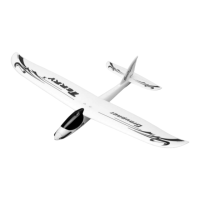
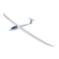
Assembling the STARLET 2400
The tailplane
Please don’t start assembling the model until you have checked the kit components
and the building instructions, and are familiar with the construction procedure. If you
are not happy with any component, kindly return it to your model shop without delay,
before you have modified it in any way. Remove one arm from the servo output
levers as shown in the photo. Set the servos to centre from the transmitter, then fit
the output levers on the servo output shafts.