This document provides instructions for assembling, operating, and maintaining the JODEL ROBIN DR 400/180 model aircraft. It is designed for use with internal combustion motors up to 40 cm³ or electric motors, and requires a HoTT radio control system with 5 functions.
Function Description
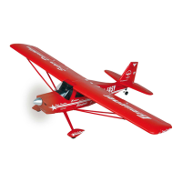
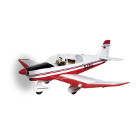
The JODEL ROBIN DR 400/180 is a pre-fabricated RC model aircraft designed for hobbyists. It can be powered by either an internal combustion engine or an electric motor. The model requires assembly, which involves installing servos, control horns, landing gear, tailplane, motor (or electric motor), fuel tank (for IC version), and cockpit canopy. The model is controlled via a radio control system, allowing for manipulation of ailerons, elevators, rudder, and landing flaps. An aero-tow mechanism can also be installed.
Important Technical Specifications
- Wingspan: Approximately 2200 mm
- Fuselage length (without spinner): Approximately 1640 mm
- Wing area: Approximately 84 dm²
- Tailplane area: Approximately 18.4 dm²
- Total wing area: Approximately 102.4 dm²
- All-up weight (depending on equipment): Approximately 9000 g
- EWD (Einbau-Winkel-Differenz, or incidence angle difference): 0-0.5 degrees
- Centre of gravity: Approximately 130-140 mm behind the leading edge
- Recommended internal combustion motors: OS MAX FS 200 S (32.4 cm³) or Petrol motor GT 33 (33 cm³)
- Recommended electric motor: COMPACT 740 Z
- Required radio control system: At least 5 control functions and 10 servos. Transmitter must be capable of servo rotation reversal.
- Recommended receiver battery: Two GRAUPNER 5N-5000 NIMH (Order No. 98903.5)
Usage Features
Assembly:
The model is extensively pre-fabricated, but careful assembly is crucial for its rigidity and flight characteristics. Before starting, read the entire construction diagram and instructions, and check for completeness of parts. When screwing into wood, apply casein glue to prevent loosening.
- Control Horns: Sand the surfaces of GRP control horns to ensure adequate adhesion. Insert them into the pre-cut slots with a dab of glue.
- Servos: Install servos in their mounts, fastening them with screws. Use rubber grommets and brass hollow rivets. Pull servo cables through wing and tailplane halves using a thin string. Extend servo cables with appropriate extension cables, securing connections with heat-shrink tubing or fast-setting glue. Set servos to the middle position using the RC system before installing servo levers.
- Pushrods: With servos and rudders in neutral, screw together pushrods for ailerons, landing flaps, and elevators. Adjust lengths and secure with thread lock fluid (e.g., UHU schraubensicher) and lock nuts.
- Hinges: Secure landing flap hinges with heat-shrink tubing. Screw hinges into marked positions on the underside of the wings, ensuring axes of rotation are equidistant from the trailing edge. Align with an engineer's square or protractor.
- Landing Gear: Melt free the slot for the landing gear wire with a hot soldering iron. Place the undercarriage leg into the slot to mark attachment points for tabs and the wheel fairing support block. Drill pilot holes and screw these components to the wing.
- Wheel Fairings: File the inside of the fairings slightly. Install wheels with collets and grub screws, applying UHU thread-lock fluid to grub screws. Ensure wheel covers face outwards and fairings are parallel to the fuselage centreline.
- Landing Searchlight: Fit two LEDs into the white plastic holder and secure with UHU Power all-purpose adhesive. Trim the holder to fit the wing recess. Route connecting leads to the root rib and glue the holder in place. Fix glazing with clear adhesive tape.
- Tailplane and Vertical Stabiliser: The vertical stabiliser can be glued or screwed on. If screwing, pull elevator servo extension cables into the fuselage first. Test fit the horizontal stabiliser with the Ø 12 mm aluminium tube, routing extension cables through its openings. Attach tailplane halves to the fuselage using the aluminium tube and four M3x16 Allen screws.
- Rudder: Fasten the rudder to the horizontal stabiliser using steel wire. Assemble pull cables. Attach rudder servo to the servo plate at the front of the fuselage. Install pull cables to the servo lever, adjusting for a centred rudder when the servo is centred.
- Nose Gear: Fix the fairing support block to the nose gear with an M4 Allen screw and nut. Fix the noseleg in its brackets by tightening the screw in the collet. Assemble pull cables. Ensure the nose gear is in neutral when the servo is centred. Attach the wheel fairing to the support block with four self-tapping screws. Fit the nosewheel onto the axle and secure with two collets.
- Aero-tow Mechanism: Screw the mechanism into the hole behind the canopy, applying UHU thread-lock fluid. Shorten the aluminium part for free clevis movement and adjust rods. Operate with a momentary switch on the joystick, setting servo travel accordingly.
- Fuel Tank (IC version): Slip plastic tubing onto the fuel tank clunk pick-up. Push the free end onto one of the stopper tubes, ensuring free movement. Heat plastic tubes to bend them: one down for filling, one up for overflow. Extend tubes to reach top and bottom of the tank. Push the stopper over the tank throat and tighten the Philips-head screw until sealed (check underwater for bubbles). Connect fuel tubing to the stub tubes, marking for motor, overflow, and filler. Connect clunk tube to carburettor, route overflow downward, and filler tube through a drill hole in the motor bonnet (seal with a plug after filling). Fasten attachment block with two screws. Connect/glue the tank and throttle servo into the fuselage using brackets.
- Motor Installation (IC version): Drill Ø 6 mm holes in the firewall for rubber damping elements and engine attachment. Cut four 30 mm pieces from the aluminium pipe. Place an aluminium bushing on each side of these pieces and screw the motor to the bulkhead. Cut protruding bolt ends flush with nuts. Adjust throttle rod so carburettor is half open when the servo is centred. Adjust servo travel to stop the engine when the throttle stick and trim are fully back.
- Choke Flap (IC version): Install choke flap rods, angled for activation through the engine bonnet opening. Ensure it doesn't interfere with the propeller arc.
- Silencer (IC version): Attach silencer to the motor with two bolts and seal.
- Engine Bonnet (IC version): Cut openings for silencer, spark plugs, etc. Position bonnet with 2 mm clearance from the spinner base plate. Mark attachment points by cutting four strips of scrap wood, drilling Ø 3 mm holes, fastening to fuselage with M3 Allen screws, and taping in place. Unscrew Allen screws, push bonnet under strips (1.5-2 mm from spinner base plate), and mark attachment points on the bonnet. Attach bonnet with four Allen screws.
- Electric Motor Installation: Attach electric motor to the bulkhead using the included motor bulkhead, bolts, nuts, cylindrical aluminium bushings, and sections of aluminium pipe. Cut four equal length pieces from the aluminium pipe to achieve a 160 mm distance between bulkhead and spinner ground plate. Motor rests on these stilts. Cut hexagonal bolts flush with nuts. Mark and attach the electric motor to the bulkhead. Fasten the speed controller to the bulkhead.
- Cockpit Canopy: Glue seat backs and pilot figure in position. Attach cockpit canopy to the frame using small pan-head self-tapping screws. Use a strip of tape around the edge for a uniform fit.
- Final Work: Fit and glue navigation lights, hatch covers, and aerials.
Balancing:
Balance the model with an empty fuel tank (IC version) or inserted drive batteries (electric version). Support the model about 130-140 mm aft of the wing's leading edge, ideally in inverted flight. The model should balance horizontally or with the nose slightly downward. Adjust the centre of gravity by shifting receiver batteries. Before flying, set transmitter trims to centre and ensure all control surfaces are centred.
Rudder Deflection (Normal Flying):
- Ailerons: 25 mm up and 9 mm down
- Elevators: 20 mm up and down
- Rudder: 35 mm left and right
- Landing flaps (Take-off): 15 mm down
- Landing flaps (Landing): 60 mm down
- Set exponential values of 30% at the transmitter.
Important Operating Notes:
- Ensure rods move freely and through their entire controllable path.
- Control Directions:
- Joystick right: Rudder right.
- Elevator stick back (towards stomach): Elevators upward.
- Aileron stick right: Right aileron upward, left aileron downward.
- Throttle stick forward: Motor full power.
- Throttle stick and trim fully back: Engine stops.
- Landing flaps are best activated via a three-position switch.
Safety Notes and Warnings:
- General: Not a toy. Not suitable for persons under 18. Operate under supervision of an adult. Operator must be in full possession of faculties (no alcohol/drugs). Use only for manufacturer's intended purpose (not for carrying people).
- Assembly: Build carefully according to instructions. No independent changes.
- Operation: Be careful and thoughtful. Model flying requires learning; seek help from experienced flyers or clubs.
- Centre of Gravity/Control Surfaces: Always observe information and adjust model accordingly.
- Radio Control System: Ensure frequency is vacant. Check RC system frequently for wear. Radio interference can cause loss of control. Never leave unattended. Keep batteries fully charged.
- Warnings: Do not ignore warnings; they refer to potentially fatal or damaging situations. You are responsible for safe operation.
- Propellers/Rotating Parts: Constant risk of injury. Keep body parts away. Loose clothing can be sucked in.
- Spectators: Ensure passers-by/spectators are aware of dangers and keep a safe distance (at least 5 m).
- Temperature: Fly only in "normal" outside temperatures (-5°C to +35°C); extreme temperatures can affect battery capacity and materials.
- Fuel (IC version): Poisonous. Avoid contact with eyes/mouth. Store in clearly marked containers out of reach of children.
- Motor Operation (IC version): Never run in closed rooms (produces deadly carbon monoxide). Operate only outdoors.
- Adhesives/Paints: May be hazardous; observe manufacturer warnings.
- Flammability (IC version): Fuel is highly flammable. Keep away from open flames, heat, sparks. Do not smoke near fuel.
- Heat (IC version): Motor and shock absorbers get very hot. Wear protective gloves when making adjustments. Fires can be caused.
- Exhaust (IC version): Poisonous and hot exhaust, plus hot liquid combustion residue. Can cause burns.
- Post-Operation (IC version): Remove residual fuel from tank and motor.
- Pre/Post-Flight Check: Carefully check model and attachments for damage. Do not fly if a fault is found.
- Starting (IC version): Use an electric starter or wooden dowel with watering hose.
- Noise (IC version): Model motors can be loud (>85 dB(A)). Wear ear protection. Never start without a silencer. Avoid running motors when people expect peace.
- Propeller Turning: If propeller turns on sandy ground, it can hurl sand/dust. Wear protective goggles.
- Spark Plug/Lead: Ensure they don't tangle with turning propeller or other rotating parts. Check throttle linkage.
- Carrying Model: Take particular care with engine running. Hold rotating parts away from you.
- Fuel Supply (IC version): Keep adequate supply. Don't fly until all fuel is used up.
- Flight Path: Never fly directly over or towards people.
- Location: Keep safe distance from residential areas (at least 1.5 km). Join a club and fly at approved sites. Keep clear of high-tension overhead cables.
- Working on Engine: Ensure secure footing and hold model securely.
- Take-off/Landing: Keep strips free of unauthorised people and obstacles.
- Visibility: Keep model in sight during entire flight. Give way to manned aircraft.
- Control: Never operate from public roads, squares, playgrounds, parks, sports grounds. Maintain full control.
- Engine Stop (IC version): Throttle must be adjustable to close carburettor barrel completely. If not, pinch fuel line or pull connecting tube. Never stop by grasping flywheel, propeller, or spinner.
- Public Safety: Ensure operations do not endanger public safety, property, or order.
- Legal: Model aircraft are aircraft and subject to legal regulations. Consult "Modellflugrecht" (Order No. 8034.02). Landowner permission and insurance are mandatory for IC models. Regulations for radio control systems must be observed.
- Responsibility: These notes highlight dangers of careless/irresponsible work. Model flying can be creative, instructive, and relaxing with care.
Manufacturer's Declaration:
Graupner GmbH & Co. KG is liable for material defects or manufacturing faults in products distributed in Germany and purchased by a consumer (§ 13 BGB). This obligation is to correct defects within described limitations. Claims are not valid for natural wear, competition use, incompetent/improper use (including incorrect installation), or external influences. This declaration does not affect consumer's legal or contractual rights.
Extent of Guarantee: Repair or replace defective goods at manufacturer's discretion. No further claims, especially for cost reimbursement or consequent damages, unless allowed by statute.
Guarantee Requirements: Purchaser must make written claim with original proof of purchase (invoice, receipt, delivery note) and guarantee card. Defective goods sent at purchaser's cost. State defect accurately. Goods transported at consumer's risk.
Duration of Validity: 24 months from purchase date by consumer from a dealer in Germany. Claims made after this period, or without required evidence, forfeit rights.
Limitation by Lapse of Time: If claim not acknowledged within claim period, all claims expire after six months from claim time, but not before end of claim period.
Applicable Law: Based exclusively on German Law, excluding international private law and UN retail law.
Maintenance Features
- Pre-flight Check: Check correct functioning and range before every flight. Screw in and extend transmitter aerial. Switch on transmitter, then receiver. Check control surfaces for proper function and deflection. Repeat with motor running (model held securely). Seek help from experienced person for first flights.
- Care: Clean model carefully after every flight. Remove dirt from propeller. Clean model and RC components with suitable agents.
- Storage: If not operated for a considerable time, clean and re-lubricate all moving parts.
- Batteries: If using dry cells, never recharge them. Only rechargeable batteries can be recharged. Charge batteries and check radio control system range before each take-off. Transmitter and receiver batteries must be charged.
- Storage Conditions: Remove all batteries before transport and storage. Do not subject model to intense humidity, heat, cold, or dirt.
- Transport: Protect model and RC equipment from damage during transport.