GRAUPNER GmbH & Co. KG D-73230 KIRCHHEIM/TECK GERMANY
Modifications reserved. No liability for printing errors 11/2011
20
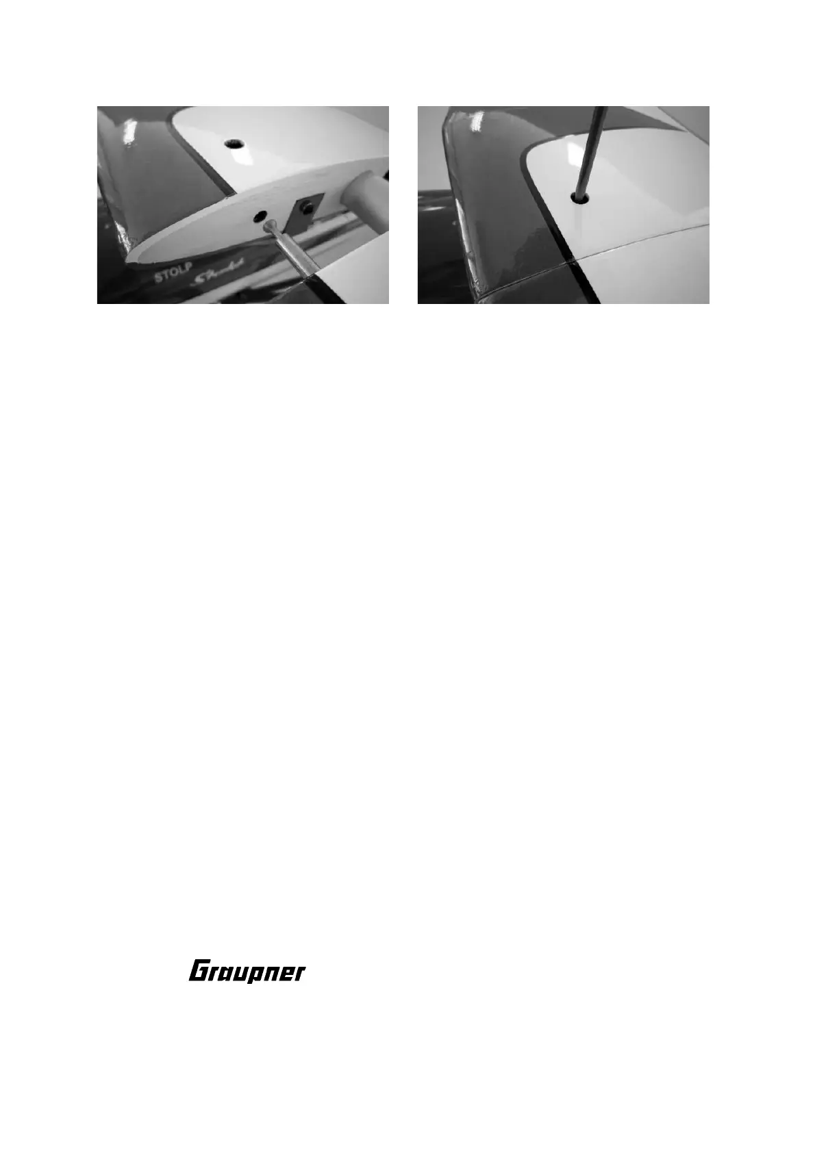
Slide the two tailplane panels onto the aluminium joiner tube and push them up to the
fuselage. Connect the extension leads, then push the panels in until the tapered
retainer engages in the yoke.
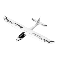
Balancing the STARLET 2400
With the fueltank empty, or the flight packs in place, support the model under the
wing roots adjacent to the cabane at a point about 160 - 170 mm aft of the root
leading edge. If the Centre of Gravity is correct, the model will now balance level,
ideally with the nose angled slightly down. If necessary, adjust the position of the
receiver bat-teries until the CG is at the stated point. Before flying the aircraft, set the
transmitter trims to centre and ensure that the control surfaces are also exactly at
neutral.
Control surface travels
Ailerons 25 mm up, 9 mm down
Elevators 20 mm up, 20 mm down
Rudder 35 mm to right and left
We recommend setting 30% Exponential on all control surfaces at the transmitter.
Important:
When fitting and adjusting the various linkages you should ensure that they move
freely, without binding, are able to move to their full extent - including trim travel - and
are not obstructed mechanically at any point.
When you move the rudder stick to the right, the rudder should also deflect to the
right (left stick: left rudder). Pull the elevator stick back towards you, and both
elevators must deflect up (stick forward: elevator down). If you move the aileron stick
to the right, the right aileron should rise, the left aileron fall. When you move the
throttle stick forward, the engine (or electric motor) should run at full power; pull the
throttle stick back, and the engine should idle (or stop). We recommend assigning the
landing flaps to a three-position switch.
Now all that remains is for us to wish you many hours of fun and pleasure flying your
STARLET 2400.
Yours - the team !
 Loading...