GRAUPNER GmbH & Co. KG D-73230 KIRCHHEIM/TECK GERMANY
Modifications reserved. No liability for printing errors 11/2011
19
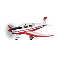
Install the PRX 5A ON / OFF switch in either the right-hand or left-hand fuselage
side.
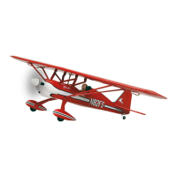
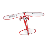
The windscreen is fixed to the cockpit cover using small screws, as shown in the
photo below. The front edge should be sealed using a strip of clear adhesive tape.
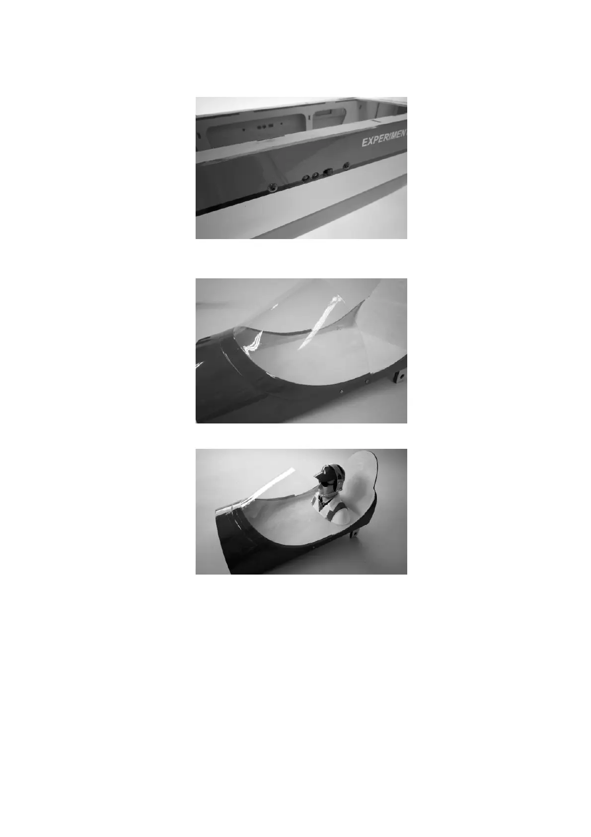
The dummy pilot can now be glued in the cockpit using Stabilit Express.
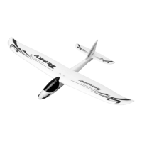
Assembling the STARLET 2400
It is advisable to connect two extension leads, Order No. 3935.65, to receiver output
sockets 2 and 5 permanently, as this makes it easier to connect the aileron servo
leads from the wings when the model is rigged. Run the fixed extension leads up the
cabane, and fix them to the struts with adhesive tape. They should exit the openings
in the root ribs of the wing centre section. Fit the joiner tube through the centre
section and slide the outboard wing panels onto it. Plug the two aileron servos into
the extension leads in the centre section, then push the wings up against the centre
section, and rotate the retainers to fix the panels in place.
 Loading...