Firmware updates for the transmitter RF module can be transferred via the DATA or telemetry interface
in conjunction with a PC running Windows XP, Vista or 7. For this you also require the USB interface,
Order No. 7168.6, and the adapter lead, Order No. 7168.6A, which are available separately.
The programs and fi les required for this are available from www.graupner.de in the Download area for
the corresponding products.
See also chapter 4.1.
04 Getting Started Graupner HoTT 2.4
3. Receiver
3.1 Connections
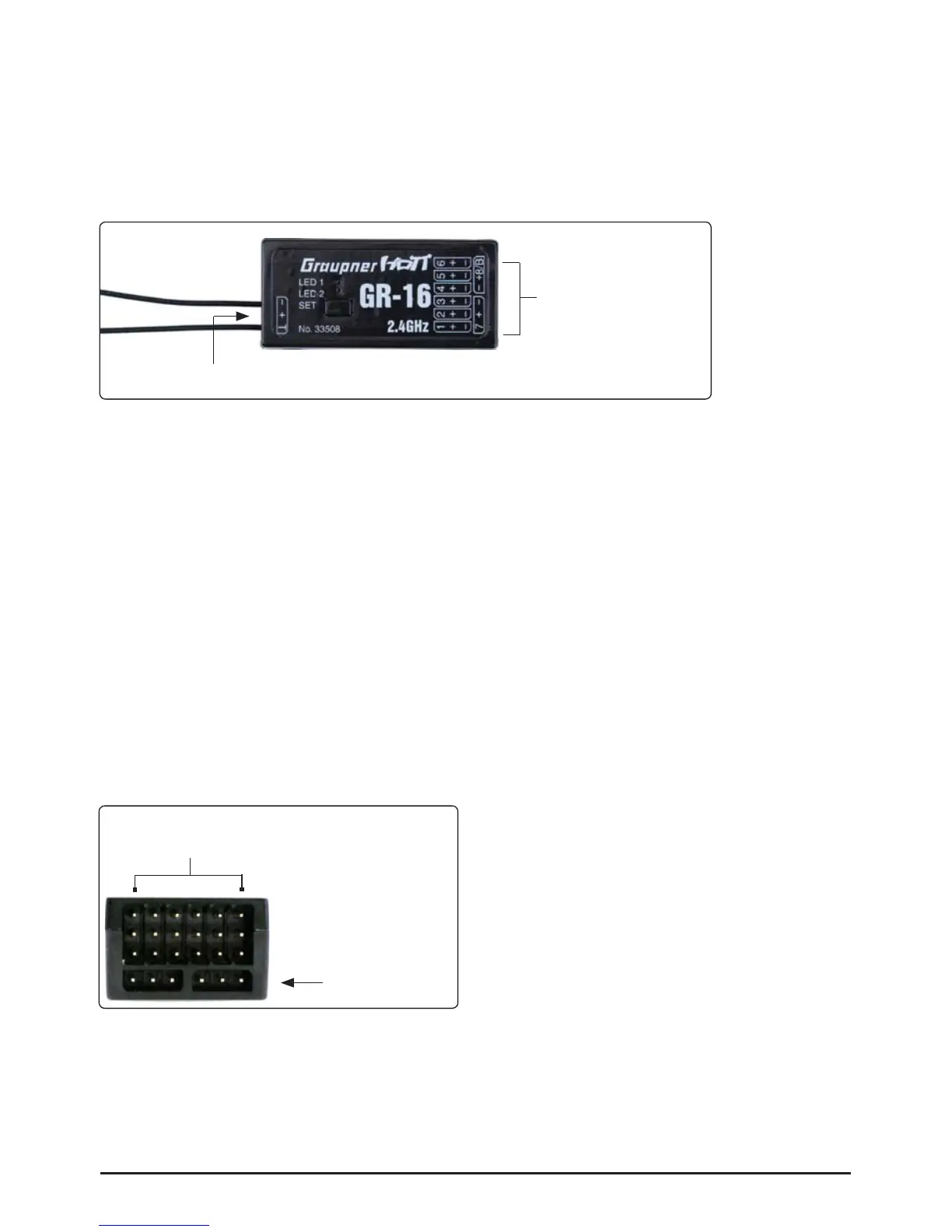
Plug the servos into the row of sockets on the right-hand end of the receiver. The connector system is
polarised; note the small chamfer on one edge. Never use force - the plugs should engage easily and
fully. The socket polarity is also marked on the case: brown wire (-), red (+) and orange (signal).
The servo sockets of the Graupner-HoTT 2.4 receiver are numbered. The socket marked “- +/B” is
intended for the battery. If necessary, a servo can be connected to this socket in parallel with the power
supply; a Y-lead (Order No. 3936.11) is required for this.
It is also possible to program the channel 8 for the sum signal using a Graupner HoTT transmitter or the
SMART-BOX (Order No. 33700). This is important for certain optional devices which require this signal.
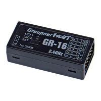
Power supply for receiver 33508, 33512
When using High Power servos, connect the receiver power supply/s preferably to the vertical ports of
the receiver. If necessary, the servos can be connected to this sockets in parallel with the power supply;
a Y-lead (Order No. 3936.11) is required for this.
The lower sockets (33508 and 33512) should not be used, because an increased voltage drop occurs.
When using a dual power supply, use the sockets on the outside:
Receiver 33506/33508 (GR-12/GR-16): Channel 1 and 6 (or 2 and 5)
Receiver 33512 (GR-24): Channel 11 and 12
The socket marked “T” - telemetry interface - on the left-hand end of the receiver is intended for the
optional telemetry sensors. This socket is also used for loading fi rmware updates in conjunction with the
USB interface. This socket is also polarised; note the small chamfer on one edge. Never use force - the
plugs should engage easily and fully. The socket polarity is also marked on the case: brown wire (-), red
(+) and orange (T).
Servo sockets
Programming socket
RECEIVER 33508
Channel 1 and 6
do not use