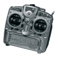
Do you have a question about the GRAUPNER mx-16 HOTT and is the answer not in the manual?
General guidelines for environmental protection and product disposal at the end of its life cycle.
Important safety recommendations and handling instructions for the radio control system and its components.
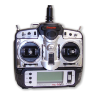
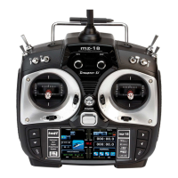
Details the components and features of the mx-16 HoTT radio control set.
Instructions on powering the transmitter and receiver, charging, and basic operation.
Information on the headphone socket for audio output and voice messages.
Details on connecting the transmitter to a PC for updates and settings.
Information on the data socket for connecting the Smart-Box.
Explanation of the DSC socket's function as a trainer/simulator interface.
Information on using the micro-SD card slot for data storage and firmware updates.
Overview of the transmitter's screen layout and keypad functions for navigation and input.
Accessing hidden menus for language selection and screen contrast adjustments.
How to select which sensors' data is displayed on the transmitter.
Details the information displayed for the receiver, including signal quality and voltage.
Displays data from General Engine or General Air modules, including battery and sensor readings.
Information on displaying rotational speed measured by a rev-count sensor.
Displays altitude, climb, and sink rate data from the Vario module.
Displays GPS positional data, speed, altitude, and reception quality.
Describes the function fields displayed on the screen and how they are activated.
Details the display of rotary controls and their interaction with trim positions.
Theoretical considerations for operating multiple models and safety aspects of 2.4 GHz band usage.
Reminder to charge the transmitter battery before first use and details on the warning threshold.
Step-by-step guide on how to switch on the transmitter and manage the RF signal.
Explanation of the low-voltage warning system and its adjustable threshold.
Notes regarding product registration and receiving update notifications via email.
Detailed steps for updating the transmitter software using a PC and USB interface.
Procedure for restoring the transmitter firmware using the emergency program in case of update failure.
General information and notes for setting up the GR-16 receiver.
Details on connecting the receiver, binding process, and LED indicators.
How the receiver's power supply voltage is displayed on the transmitter screen.
Explanation of temperature warnings and their configurable thresholds.
Guidelines for connecting servos to receiver sockets, including polarity and numbering.
Procedure for resetting the receiver to factory default settings.
Key notes on firmware compatibility, battery state, and connection stability during updates.
Instructions for installing the necessary driver software for the USB interface.
Steps for connecting the receiver to the PC using the USB interface and adapter lead.
Detailed procedure for updating the receiver firmware using the upgrade software.
Steps for connecting the receiver to the PC for backing up settings.
How to select the correct COM port for the USB interface within the receiver setup program.
Procedure for reading out receiver data and displaying current values.
Instructions on how to save the current receiver configuration to a file on the PC.
How to load backed-up data back into the receiver using the Receiver Setup program.
Recommendations for installing the receiver, including aerial placement and isolation.
Essential considerations for a reliable airborne power supply for the receiver, including battery selection and capacity.
Explanation of what a control function is and its role in model control.
Defines transmitter controls as the physical elements operated by the pilot.
Explanation of function input points and their relation to transmitter controls.
Defines a control channel as the signal containing information for a servo.
Explains the purpose of mixers in coupling control functions and servos.
Describes the function of various switches for programming options and control assignments.
Explains how transmitter controls can be used to switch functions automatically.
Step-by-step guide for assigning a switch to a function.
How to correct the direction of a switch assignment if it is reversed.
Procedure for erasing an assigned switch.
Explanation of using transmitter controls like sticks for automatic function control.
Details on digital trim function and the special cut-off trim for Ch 1.
Describes the visual and audible feedback provided by the digital trim system.
Specific application of the Ch 1 trim for glowplug motors in fixed-wing models.
How the Ch 1 trim functions in helicopter mode, particularly with the throttle limit function.
Explanation of aileron differential for compensating adverse yaw in fixed-wing models.
Details flap differential for camber-changing flaps.
Describes the aileron-rudder coupling mixer for smoother turns.
Explains the aileron-flap mixer for linking aileron movement to flap servos.
Details the airbrake-elevator mixer for compensating airspeed changes during braking.
Describes the airbrake-flap mixer for coordinating flap deployment with airbrakes.
Explains the airbrake-aileron mixer for coordinating aileron deflection with airbrakes.
Details the elevator-flap mixer for affecting elevator response with flap deployment.
Describes the elevator-aileron mixer for reinforcing elevator response with ailerons.
Explains the flap-elevator mixer for pitch trim compensation during flap operation.
Details the flap-aileron mixer for linking flap signal to aileron channels.
Explains differential reduction for suppressing aileron differential during airbrake deployment.
Notes on connecting servos to receiver outputs in the correct order and important points to observe.
Explains the collective pitch function and how to set its curve.
Details the Ch 1 throttle function and its curve settings.
Explains the Ch 1 tail rotor function and its static torque compensation.
Shows the standard servo output assignments for model helicopters.
Guide to selecting and reserving a new model memory slot.
Procedure for selecting an existing or free model memory.
How to erase a selected model memory.
Instructions for copying model data between memory slots.
How to export model data to an SD card for backup or transfer.
How to import model data from an SD card into the transmitter.
Core settings for fixed-wing models, applied to the active model memory.
How to enter and manage a name for the model memory.
Selecting the arrangement of control functions on the transmitter sticks.
Configuring the throttle control and its associated settings, including idle and cut-off.
Setting a delay for control channel 8, used for flight phase transitions.
Selecting the tail type (normal, V-tail, delta, etc.) for the model.
Configuring aileron and flap servo arrangements and their mixer functions.
Setting up and assigning switches to the built-in stopwatch and flight timer.
How to switch timer functions between count-up and count-down modes.
Setting up and naming additional flight phases (2, 3, and 4) and assigning switches.
How to swap receiver servo outputs for flexible channel assignment.
Procedure for binding the receiver to the transmitter for communication.
Instructions for performing a range check to test system operation and interference rejection.
How to manually switch the transmitter's RF signal on and off for specific models.
Core settings for model helicopters, applied to the active model memory.
How to enter and manage a name for the helicopter model memory.
Selecting the arrangement of control functions for helicopters on the dual-axis sticks.
Selecting the swashplate type based on the number of servos used for collective pitch control.
Setting the direction of rotation for the main rotor.
Setting the direction of operation for the throttle/collective pitch stick and its minimum position.
Defining the "motor OFF" position for throttle servo or speed controller in emergency situations.
Basic procedures for assigning transmitter controls and switches for fixed-wing models.
Step-by-step guide for assigning controls and switches to functions.
Details on assigning transmitter controls and switches to function inputs.
Adjusting transmitter control travel symmetrically or asymmetrically.
Basic procedures for assigning transmitter controls and switches for helicopter models.
Step-by-step guide for assigning controls and switches to functions.
Details on assigning transmitter controls and switches to function inputs.
Adjusting transmitter control travel symmetrically or asymmetrically.
Setting up the throttle limiter function for helicopter motor control.
Assigning a transmitter control for adjusting gyro gain.
Explanation and application of the throttle limit function for controlling helicopter motor speed.
Explains the servo settings for direction, center, and travel.
How to offset the servo travel center for fine-tuning neutral positions.
Adjusting servo travel symmetrically or asymmetrically.
Details on pre-programmed coupling functions for fixed-wing aircraft.
Explains the fundamental purpose and operation of mixers in radio control systems.
Illustrates the use of a V-tail mixer for linking elevator and rudder controls.
Details aileron differential for compensating adverse yaw.
Explains flap differential for camber-changing flaps.
Describes the aileron-rudder mixer for smoother turns.
Details the airbrake-elevator mixer for compensating airspeed changes during braking.
Describes the airbrake-flap mixer for coordinating flap deployment with airbrakes.
Explains the airbrake-aileron mixer for coordinating aileron deflection with airbrakes.
Explains the crow/butterfly mixer configuration for glide path control.
Details the flap-aileron mixer for linking flap signal to aileron channels.
Explains differential reduction for suppressing aileron differential during airbrake deployment.
Overview of helicopter mixer functions and flight phase settings.
Settings for auto-rotation descent and landing procedures for helicopters.
General information on using freely programmable mixers for custom control setups.
Details on the three freely programmable linear mixers available for custom configurations.
Explanation of using a switch channel as a mixer input for constant signals.
Practical examples of setting up free mixers for specific applications.
Explains swashplate mixers for collective pitch, roll, and pitch-axis control in helicopters.
Details on how swashplate mixers superimpose functions for collective pitch, roll, and pitch-axis.
Visual display of current servo positions, taking into account various settings.
General transmitter settings that apply across all model memories.
Selecting the transmitter's battery type (NiMH or LiPo).
Setting the voltage threshold for the low-voltage warning.
Adjusting the sensitivity of the transmitter's touch-keys.
Adjusting the screen contrast for optimal legibility.
Setting the duration of the screen backlight.
Configuring the transmitter's country setting to comply with RF regulations.
Adjusting the volume of speech output for telemetry and warnings.
Adjusting the volume of the transmitter's internal sounder.
Explanation of the Fail-Safe function and its importance for safety.
Steps for programming the Fail-Safe settings for receiver outputs.
Introduction to the Telemetry menu and its functions.
General operation of the Telemetry menu, including navigation and parameter adjustment.
Describes the RX DATAVIEW screen for viewing real-time receiver data.
Explains how signal quality is displayed and its meaning.
Details the receive performance measurement and its interpretation.
Information on monitoring receiver temperature and associated warnings.
Displays the duration of lost data packets during transmission.
Monitoring the receiver's operating voltage and low-voltage warnings.
Shows the lowest receiver operating voltage since the last power-on.
Displays values from optional telemetry sensors.
Allows selection of which sensors' data to display in the telemetry menu.
Visualizes the quality of the connection between the transmitter and receiver.
Configuration for voice output of telemetry data and warnings.
Connecting two transmitters for trainer mode operations using a trainer lead.
Instructions for connecting two transmitters using a trainer lead for operation.
Configuration settings for the Teacher transmitter in trainer mode.
Configuration settings for the Pupil transmitter in trainer mode.
Steps for preparing both Teacher and Pupil transmitters before initiating trainer mode.
Procedures and checks for operating the system in trainer mode.
How to resume trainer mode operations after power interruption or disconnection.
Overview of the Info Display menu for accessing transmitter information.
Displays transmitter-specific information including RFID, firmware, date, time, and SD card status.
Displays the transmitter's unique identification number.
Shows the installed transmitter software version number.
Setting and displaying the current date.
Setting and displaying the current time.
Displays the storage capacity and available space on the installed memory card.
General notes on RC system installation and setup for fixed-wing models.
Initial steps for programming a new model, focusing on a non-powered fixed-wing aircraft.
Using rotary controls to include an electric power system.
Using a two-position switch for ON/OFF motor control.
Using three-position switches for electric motor control with soft start.
How to control the electric motor and butterfly system using the Ch 1 stick.
Setting up a butterfly/crow system for landing aid with ailerons up and flaps down.
How to program and switch between up to four different flight phases.
Accessing base settings to assign switches for flight phases.
Adjusting trims for selected flight phases.
How to set up servos to run in parallel using transmitter software facilities.
Example of setting up two elevator servos to operate in parallel.
Example of connecting two rudders in parallel using free mixers.
General notes on installation and setup for delta and flying wing models.
Selecting tail type and servo arrangements for delta/flying wing models.
Using wing mixers for delta/flying wing models, particularly for elevator and flap functions.
Assigning transmitter controls for elevator and flap adjustments.
Basic setup procedure for a model helicopter, demonstrating logical programming techniques.
Selecting a free model memory and setting the model type to Helicopter.
Performing basic helicopter setup, including binding the receiver and setting model name, stick mode, and swashplate type.
Setting mixer ratios and directions for swashplate servos.
Assigning transmitter controls for functions like throttle limiter and gyro gain.
Setting servo travels and directions for helicopter components.
Activating the auto-rotation switch for emergency motor cut.
Adjusting flight phase settings and modifying mixer parameters.
Settings for auto-rotation descent and landing procedures for helicopters.
Setting up the throttle curve for auto-rotation and normal flight.
Setting static torque compensation for the tail rotor.
Adjusting gyro gain using transmitter controls.
Additional adjustments for flying with different rotor speeds and trim setups using flight phases.
Programming guide for F3A model aircraft, covering basic setup and specific adjustments.
Adjusting servo settings for F3A models, including travel and direction.
Activating idle trim for Channel 1 and setting the motor control.
Assigning transmitter controls for retracts and carburetor mixture.
Setting exponential values for aileron, elevator, and rudder for F3A models.
Using free mixers for aileron and flap adjustments in F3A models.
Using mixers to compensate for model inaccuracies and improve flight characteristics.
Correcting unwanted rotation caused by rudder input using elevator and aileron mixers.
Mixing elevator neutral position based on throttle setting for vertical maneuvers.
Using a mixer to correct rolling tendencies when reducing throttle.
Correcting rolling caused by aileron/flap deflection during landing approach.
Description of the PRX power supply unit and its features.
Details of the GPS/Vario module, including altitude and GPS specifications.
Details of the Vario module, including altitude and climb/descent specifications.
General sensor for models with internal combustion or electric power systems.
General sensor for models with internal combustion or electric power systems.
General sensor for electric-powered models, including Vario and temperature measurements.
Description of the Smart-Box for displaying telemetry data and changing settings.
Description of the magnetic rev-count sensor for engine modules.
Description of the optical rev-count sensor for engine modules.
Information on the USB interface required for updating receivers and sensors.
Description of the adapter lead required for the USB interface.
| Brand | GRAUPNER |
|---|---|
| Model | mx-16 HOTT |
| Category | Remote Control |
| Language | English |
