EN - 32
2. Tighten drive belt idler pivot bolt.
3. Install PTO belt on blade spindle pulleys
(see PTO Belt on page 29).
MOWER DRIVE BELT
(992219)
(Figure 20)
Removal
NOTICE: The PTO belt must be removed
from blade spindle pulleys prior to removing
mower drive belt. The PTO belt does not
need to be removed from electric clutch.
1. Remove PTO belt from blade spindle
pulleys (see PTO Belt on page 29).
2. Remove right hand belt cover.
3. Place 1/2" breaker bar into square hole
of the drive belt idler.
4. Pull bar towards front of unit and remove
belt from drive belt idler.
5. Slowly release tension from idler arm till
tension is released from spring.
6. Remove mower drive belt from center
blade pulley and right pulley spindles.
Installation
1. Install the new mower drive belt on drive
belt idler.
2. Using 1/2" breaker bar put tension on
spring moving idler toward front of deck.
3. Install the new mower drive belt on
center blade spindle pulley, right blade
spindle pulley.
4. Release tension with belt on all pulleys.
5. Check spring tension.
NOTICE: Spring should be 13.875 – 14.125"
(35.24 to 35.87 cm).
6. Install PTO belt on blade and spindle
pulleys (see PTO Belt on page 29).
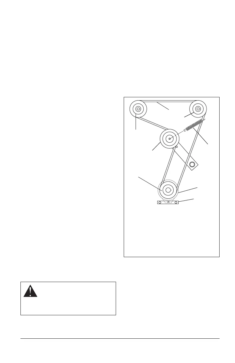
TRANSMISSION BELT
(Figure 22)
Removal
1. Remove PTO belt from electric clutch
(see PTO Belt on page 29).
2. Remove clutch anchor.
3. Slowly release the tension on the hydro
pump belt idler until all the tension is
removed from the springs.
4. Remove old hydro pump belt from right
hand hydrostat sheave first.
Installation
1. Install new hydro pump belt by
positioning belt on sheaves. Put belt
onto right hand hydrostat sheave last.
2. Replace clutch anchor.
3. Install PTO belt on electric clutch (see
PTO Belt on page 29).
STEERING CONTROL
NEUTRAL ADJUSTMENT
If the steering levers do not line up (match) or
the unit has excessive creeping when the
steering levers are in neutral, adjust as
follows.
CAUTION: Use care when
releasing idler spring tension.
Keep body parts well away from
idlers when performing this
operation.
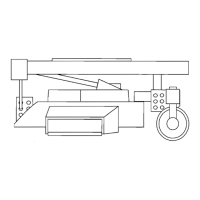
Figure 22
1. Right Hand Hydrostat
2. Hydro Belt
3. Left Hand Hydrostat
4. Spring
5. Clutch
6. Clutch Anchor
7. Engine Sheave
8. Idler
1
2
3
5
6
7
8
4