GB - 10
Unpack Unit
Remove unit and all other components from
shipping container. Open bypass valves (see
MOVING UNIT MANUALLY on page 17).
Push unit from container onto a level surface.
Close bypass valves.
Prepare Seat
Remove nuts from seat studs in hood frame.
Peel off paper backing from foam tape and
place between hood frame and chassis. Lift
and rotate seat onto hood frame. Secure with
nuts.
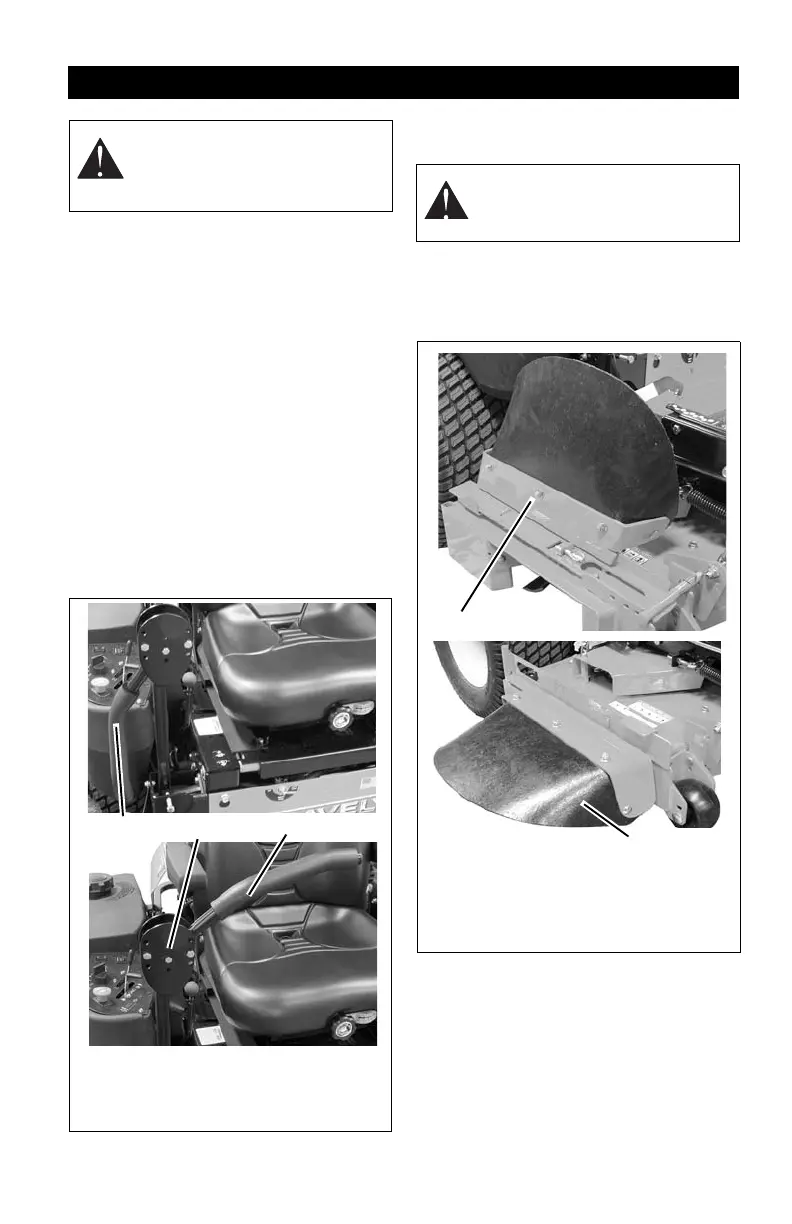
Install Steering Levers
Remove spacers, bolts, and nuts from
steering levers. Turn the steering levers into
the operating position. Re-install spacers,
bolts and nuts. Tighten hardware securely
(figure 3).
Place Discharge Chute in Operating
Position
Prior to operating the unit, remove the
discharge chute from the transport position
and place the discharge chute in the
operating position (figure 4).
ASSEMBLY
WARNING: AVOID INJURY. Read
and understand entire Safety
section before proceeding.
Figure 3
1. Steering Lever in Shipping Position
2. Spacers and Hardware
3. Sterring Lever in Operation Position
1
2
3
WARNING: Do not operate
mower unless the discharge chute
is in the operating position.
1. Discharge
Chute in
Transport
Position
2. Discharge
Chute in
Operating
Position
Figure 4
1
2