Rl
1 is what you saw in step 7 (Fig. 42). If we could connect
the scope so that it would display the current flowing
through
I31
1, we would see that current waveform is the
same as the voltage waveform. We can say that the current
flowing through a resistor is in phase with the voltage
across the resistor, and is proportional to this voltage.
Ohms Law expresses this proportionality in the formula I
=
E/R or, current
=
voltage/resistance.
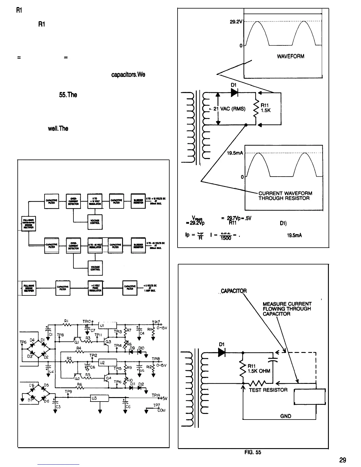
This direct correspondence of current and voltage are not
true with other components such as
capacitorswe
can dis-
play the waveform and magnitude of the current passing
through a capacitor by using the test set up shown sche-
matically in Fig.
55.The
voltage developed across the test
resistor is proportional to the current flowing through it. As
long as the resistance value of the test resistor is small
compared to the resistances in the circuit being tested, the
measurement error because of the added resistance will
be small as
well.The
high sensitivity of the oscilloscope al-
lows the current sensing test resistor to have a small resist-
ance value.
T?l7
,
.
.
.
TPl9
o+
,
TPZ
5v
FIG. 53
VOLTAGE
WAVEi=ORM
/
ACROSS RESISTOR
Tl
21
VfqMS
x 1.414
=
29.7Vp
-
.5V
(FORWARD VOLTAGE DROP
=
29.2Vp
ACROSS
Rll
.
ACROSS
01)
EP
29.2
lp=m
I===.
0195 AMPERES OR
19.5mA
FIG. 54
PROBE CONNECTION TO MEASURE VOLTAGE
ACROSS
_CAPAClTOR
PROBE CONNECTION TO
Tl
10 OHMS
SCOPE
GND
e
l
-.-
--
FIG.
55
29
 Loading...