CAPACITIVE FILTER EXPERIENCE
Purpose: To obsetve the current through and the voltage
across a capacitor when it is connected to a half wave
recti-
fier
circuit.
Equipment: Oscilloscope
Clip Lead
1000
mF
Capacitor
Test Resistor
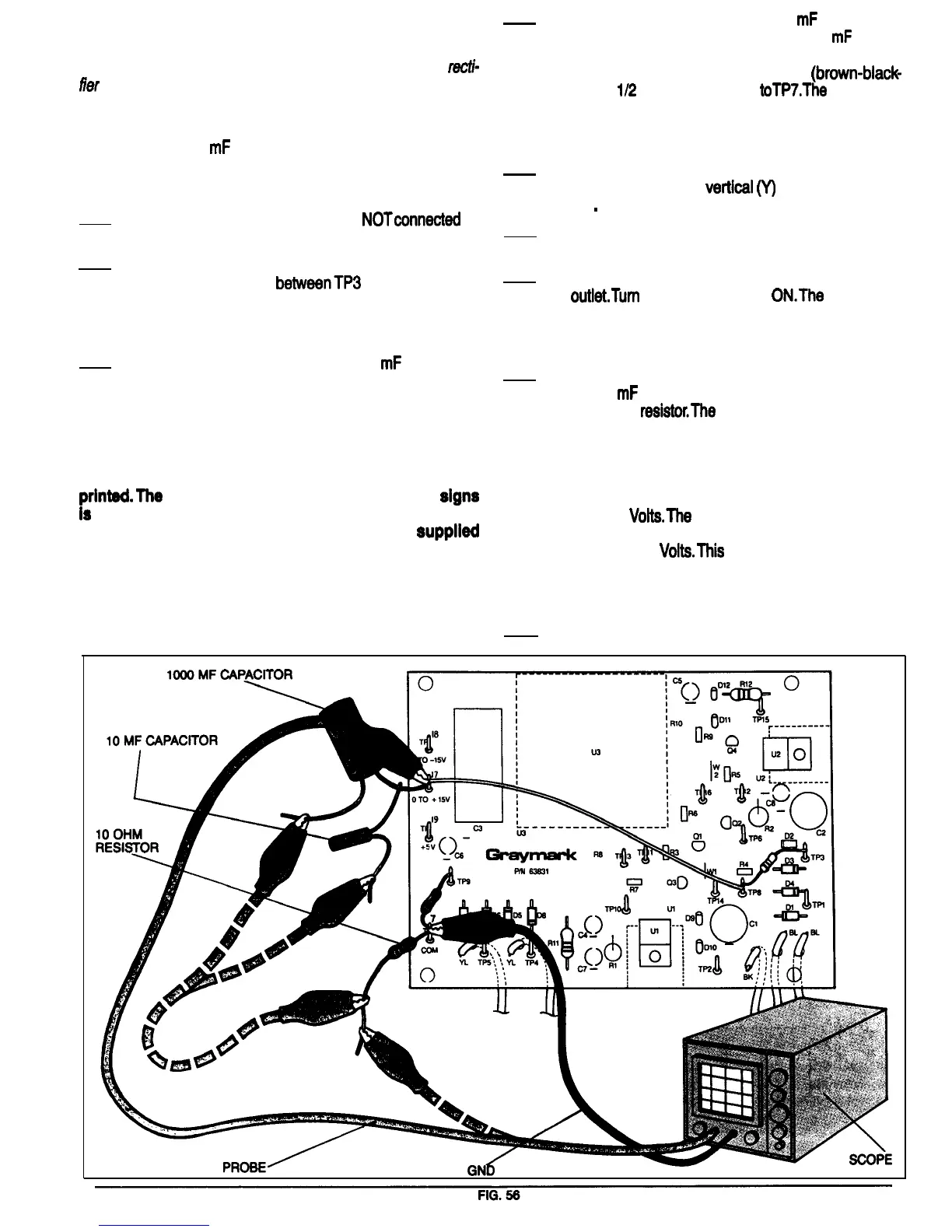
Refer to Fig. 56 for the following steps.
1.
Be sure the 808 power plug is
NOTconnected
to
a power outlet.
2. Unsolder from TP3 the anode lead of the diode
that was installed
betweenTP3
and TP8 during
the Full-Wave Center-Tapped Rectifier Test.
Bend the anode lead so that is not touchingTP3
or any of the other parts or the PCB.
3.
Solder the positive lead of a 1000
mF
35 Volt ca-
pacitor toTP17. Make sure that the red wire from
TP8 remains soldered to TP17.
NOTE: The capacitors supplied in your 808 kit ail are
of the electrolytic type, and have both leads coming
out of one end of the body of the capacitor. On the side
of the capacitor there will be one or more minus signs
printed/The
lead that is closest to these minus
signs
Is
the negative lead of the capacitor; the other lead is
the positive lead. Also, the capacitors are
supplled
with the positive leads longer than the negative leads
as a further means of determining polarity.
It is important to observe polarity when using electro-
lytic capacitors. Failure to do so may result in damage
to the capacitor and other components.
4. Solder the positive lead of a 10
mF
50 Volt ca-
pacitor to the positive lead of the 1000
mF
capac-
itor that you soldered to TP17 in step 3. Solder
one of the leads of the 10 Ohm
(brown-black-
black)
1/2
Watt test resistor
toTP7.The
other lead
of this 10 Ohm resistor and the negative leads of
the two capacitors are not connected to anything
at this time.
5. Adjust the scope to display a 30 Volt (peak) 60
Hz signal. Set the
vertical
(Y)
input coupling to
DC
.
6. Connect the scope ground lead toTP7, and the
scope input probe to TP17.
7. Connect the 808 Power Supply plug to a power
outlet.Turn
the Power Switch
ON.The
scope dis-
play should look like Fig. 57. You’ve seen this
waveform before, its the output of a half wave
rectifier.
8. Using a clip lead, connect the negative lead of
the 10
mF
test capacitor to the free lead of the 10
Ohm test
resistor.The
scope should now display
the waveform shown in Flg. 58. Adjust the sweep
and trigger controls as necessary to make the
scope display closely match the waveform as
shown in Fig. 58. Notice that the peak voltage is
about 30 Volts, and the minimum voltage is
about 9
VoltsThe
peak to peak ripple voltage is
the difference between these two voltages, that
is, about 21
Volts.This
is a very large amount of
ripple. If your stereo system were powered by a
supply with this much ripple, you would hear a
very loud 60 Hz tone whenever it was turned on.
9. Remove the 808 power plug from the outlet for
30
 Loading...