CAPACITIVE FILTER CALCULATIONS
PERCENT OF RIPPLE
This term is often used to express how “clean” or free from
periodic voltage variations a power supply output is. The
voltage output of a battery supplying power to a constant
load, such a fixed resistor, has a percent of ripple of 0.
To calculate the percent of ripple, the following formula is
used:
V
%
Ripple
=
p
x 100
average
Where:
V~a
=
the rms value of the peak to peak
ripple voltage
We can use
.707
times the peak to peak ripple volt-
age to determine the rms ripple voltage. While this
conversion is only exact for sine waveforms, it is
reasonably accurate for full-wave ripple
waveforms.
V
average
=
the average dc voltage output of the
power supply.
The dc voltage ranges of a VOM or a DMM read
the average value of a pulsating dc voltage input.
Using the above formula, calculate the percentage of ripple
in the voltage waveform shown in Fig. 59. Use 24.4 Volts
for V
avemfp
Hint: the peak to peak ripple voltage can be calculated from
the voltage values given in Fig.
59.The
positive peak of the
ripple voltage is 30 Volts. The negative peak of the ripple
voltage is
18
Volts. Both of these voltages are positive in
respect to ground. The peak to peak ripple voltage is the
difference between these two voltages, that is, 12 Volts.
Write your answer here.
CAPACITANCE REQUIRED FOR A PARTICULAR
APPLICATION
If
we were designing a power supply, ho.w would we deter-
mine the value of capacitance needed for the capacitance
filter? Lets go through the process step by step, using the
positive 0 to
15
Volt power supply of the 808 as an example.
Figure 61 is the schematic of this power supply.
1.
Determine the current required from the capacitive filter.
The rated output is
15
Volts at 300
mA.
Bleeder resistor
Rl
1 has a resistance value of 1500 Ohms. Using Ohm’s
law,
(I
=
E/R), we find the current through this resistor
is .OIO Amps, or 10
mA.
To calculate the current flowing through the
R7,
R8,
D9
and
DlO
circuit, we will have to get some values from
the ELECTRICAL CHARACTERISTICS OF THE
LM317
table in
theVOLTAGE
REGUMTOR
SECTION
of this manual. These values are the “Reference Volt-
age”, which appears across
R7,
and the “Adjustment
Pin
CurrentYThe
Reference Voltage is 1.30 Volts maxi-
mum.
R7
is a 340 Ohm resistor. Using Ohm’s law again,
the same formula as above, the current through
R7
cal-
culates to be 3.8
mA.
Since the Adjustment Pin Current
is a relatively low 100
uA
(or .l
mA)
we will ignore it. If
we wanted to include it, it would be added to the current
flowing through
R7.
Since a current of 300
mA
is not
enough to turn on the
overcurrent
protection
circuitry,(Ql,
R3
and
Q3),
there is no current flowing
a
s
30
.
0
.
Dropout Voltage
\
1
1
I
1
v
T
T
7
A/~~~=100
mV
-75 -50
-25
0
25 50 75
100 125 150
TEMPERATURE
(
C)
FIG.
60A
through these three components. Its as if they were not
there.
Adding these three currents gives us the total current
that the filter capacitor (Cl
)
must provide during the time
periods that the rectifier is not supplying current. See
Fig. 60.
Rated output current:
300.0
mA
Bleeder
(Rl
1) current:
10.0
mA
Voltage control circuit current:
3.8
mA
Total current: 313.8
mA
2.
Determine the voltage required from the capacitive filter.
The rated output is 15 Volts. To this we must add the
“Drop Out” voltage of the voltage regulator, and the volt-
age drop across the overcurrent sensing resistor Rl.
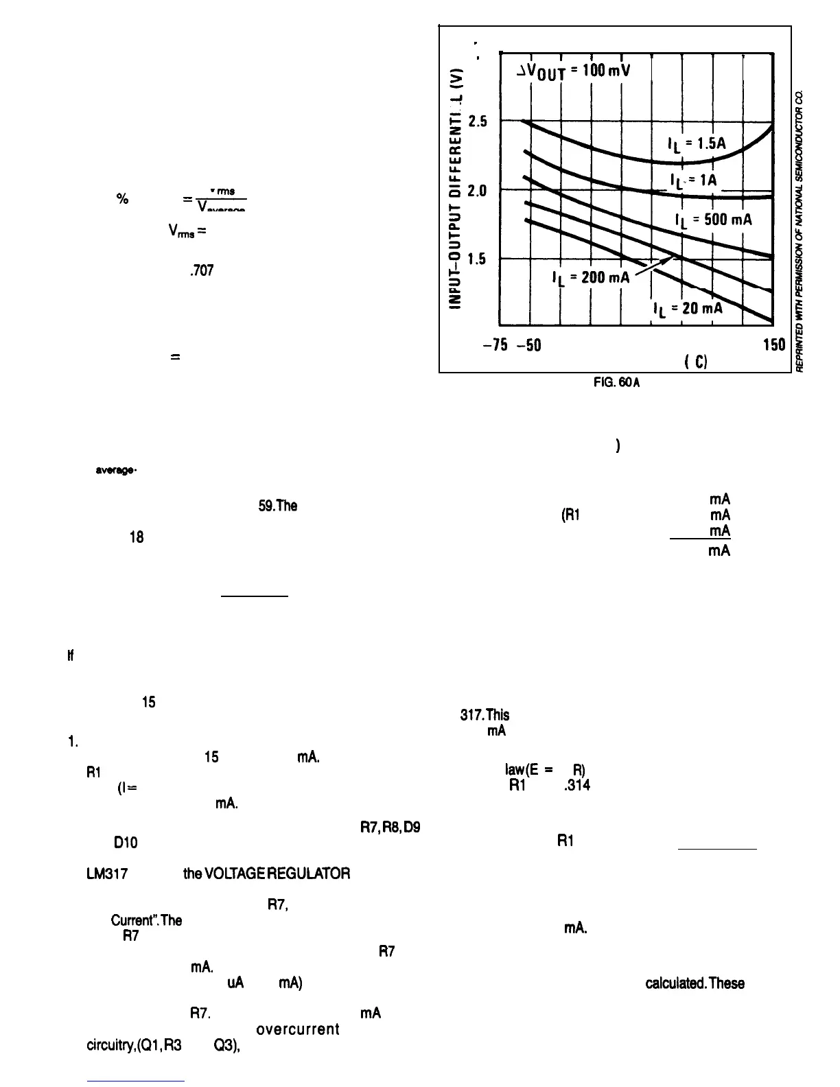
The drop out voltage of a regulator is the lowest voltage
across its input to output terminals that can exist with the
voltage regulator still functioning as a regulator. We will
get voltage from the Dropout Voltage graph, from the
National Semiconductor specification sheets for the LM
317.This
graph is shown in Fig. 60A. Using a current of
500
mA
and a temperature of 25 C, the graph indicates
the input/output differential to be about 1.8 Volts.
Ohm’s
law(E
=
I x
R)
indicates the voltage drop across
1 Ohm
Rl
to be
,314
Volts.
Rated output voltage: 15.0
Volts Regulator dropout voltage:
1.8
Volts
Rl
voltage drop:
0.314 Volts
Total Voltage: 17.114 Volts
This is the minimum voltage that Cl has to maintain be-
tween the time periods the rectifier is supplying current
if the output voltage is to be maintained at 15 Volts with
a current of 300
mA.
3.
If complete specifications for the power transformer and
rectifier diodes are available, the peak voltage at the
bridge rectifier output can be
calculated.These
specifi-
cations would have to include winding resistances, turn
ratios,. and core losses at different power levels for the
power transformer and forward voltage drops at differ-
ent current levels for the rectifier diodes.
32

 Loading...