RC
TIME CONSTANT EXPERIENCE
DISCUSSION
The time constant of the discharge of a capacitor through
a resistor is the time required for the voltage or current to
drop to 1
/e
of its value at the time the discharge began.The
symbol “e” is the base of the natural or Napierian logarithm.
It
value is 2.718. The reciprocal of e (l/e) is 0.3679.
Consider the formulas:
E
C
=
Ep
x
es*
or;
E
C
=
Ep
x
(l/e)m
Where:
EC
is the voltage across the capacitor at
the end of the discharge time period,
Ep
is the voltage across the capacitor at
the beginning of the discharge period,
e is 2.718,
t
is the discharge time in seconds,
T
Z
R
x C, in seconds,
R
is resistance in Ohms,
and C is capacitance in Farads.
If
R
is expressed in
kOhms,
C in
uFTand
t
in milliseconds
(mS);
the formula is a little easier to handle.
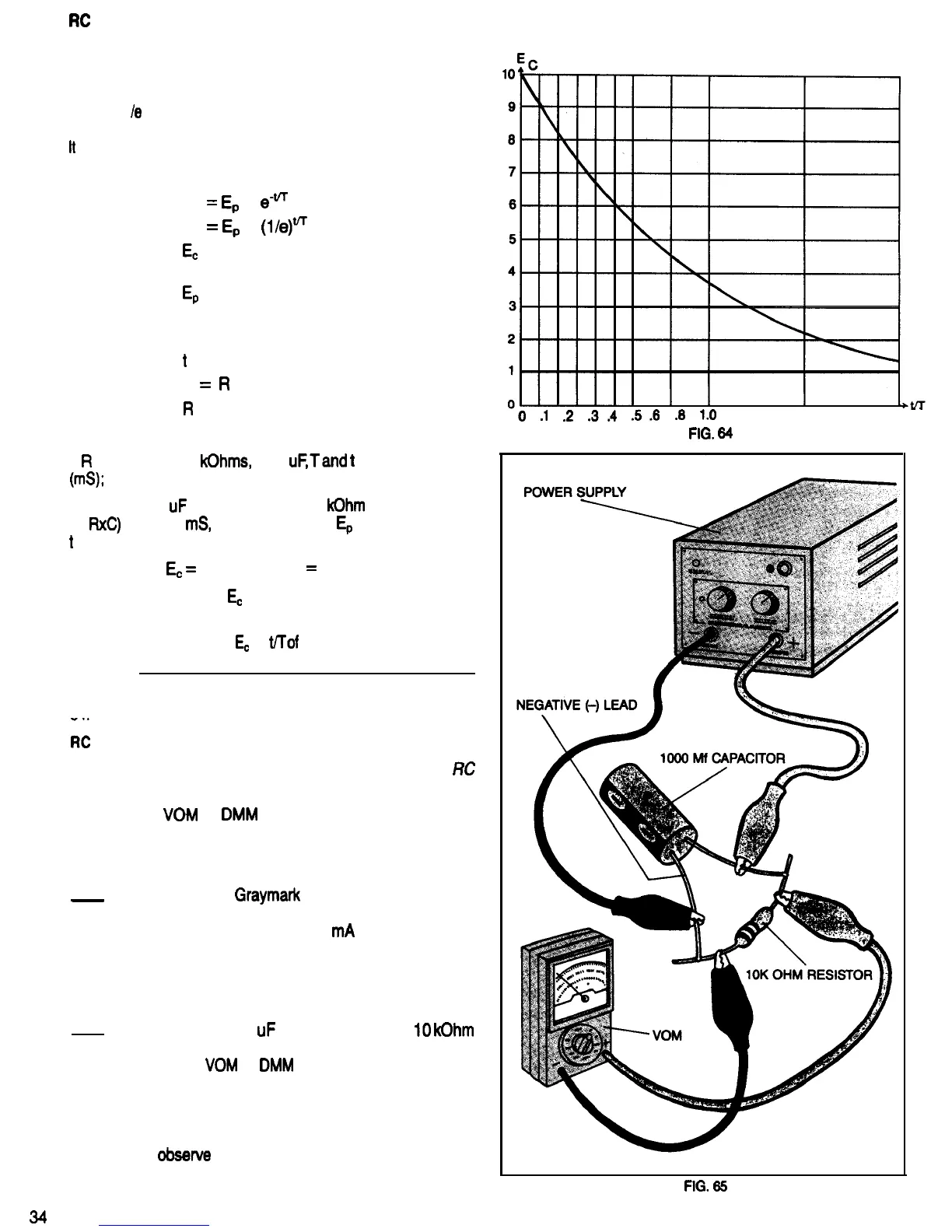
Using a 1000
uF
capacitor and a 10
kOhm
resistor,T (that
is,
RxC)
is 10,000
mS,
or 10 seconds. If
Ep
is 10 Volts, and
t
is 10 seconds,
then
EC
=
10 x 0.3679’
=
3.679 Volts.
Figure 64 is a graph of
EC
versus time, using the values giv-
en above.
Calculate the values for
EC
at
tKof
0.5 and 2.0. Record your
answers.
Compare your answers with the values you read from Fig.
64
I?;
CIRCUIT TEST
Purpose: To observe the action of an actual (hardware)
RC
circuit.
Equipment:
VOM
or
DMM
-
1.
2
.
DC Power Supply
Two Clip Leads
Watch With Second Hand or Digital Readout
A completed
Graymark
808 or 803 Power Sup-
ply, or any power supply capable of supplying 10
Volts at approximately 25
mA
or more may be
used. Be sure the power supply power plug is
Not connected to a outlet, and that the voltage
control is set for minimum voltage output. Refer
to Fig. 65 for the following steps.
Connect a 1000
uF
capacitor and the
IO
kOhm
(brown-black-orange) test resistor from your 808
kit to the
VOM
or
DMM
as shown in Fig. 65. Sol-
der the capacitor leads to the resistor leads. Do
not make a mechanical connection of the leads
before soldering, as these parts will be
unsoldered at the end of this experience. Be sure
to
obsewe
the capacitor polarity when connect-
ing the power supply and meter.
-0
.l
.2
.3.4
5.6
98
1B
1.5
2.0
-
-
FIG.
64
FIG.
65
34

 Loading...