power supply outputs evaluated under load until
satisfacto-
v
capacitance values are found. Most engineering compa-
nies use a mathematical approach for the initial design
work, and then verify the design by building and testing a
prototype. Developments in computers and software allow
tests using computer simulated prototypes, with savings in
engineering time and expense.
A value of 1000
uF
was selected for the capacitive filter of
the positive variable supply in the
Graymark
808. The se-
lection of this value was based on further calculations.
CONSTRUCTION
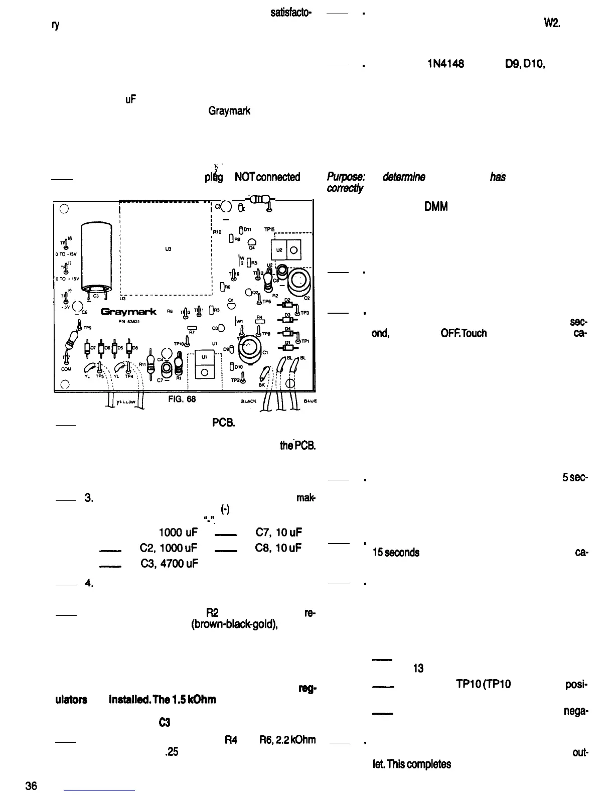
Refer to Fig. 68 for the following steps.
,
1.
Be sure the 808 power
pl$g
is
NOTconnected
to
a power outlet.
r--0-----------
--
I
;
cs
I
I
0
012
Rl2
0
=Fi=
0
I
I
-
I
I
,
RlO
011
lPl5
r----------
U3
2. Mount diode D2 on the
PCB.
Be sure that the
banded end of the diode is oriented the same as
the diode outline that is silkscreened on
thePCB.
Using a heat sink as shown in Fig. 40, solder the
diode leads to the PCB. Cut off any excess lead
length.
3.
Mount the following capacitors on the PCB,
mak
ing sure that the negative
(0)
leads are inserted
into the holes marked
“J’.
-A. Cl,
IOOOuF
_
D.
C7,lO
uF
-
B.
C2,lOOO
uF
-
E.
C8,lO
uF
-
C.
C3,4700
uF
4.
Solder all the capacitor leads to the PCB and cut
off any excess lead lengths.
5. Mount resistors RI and
R2
on the PCB. Both
re-
sistors are 1 Ohm
(brown-blackgold),
1 Watt.
Solder the resistor leads to the PCB and cut off
any excess lead length.
NOTE: The following components are being mounted
on the PCB at this time to serve as bleeder resistors
for capacitors Cl and C2 until the variable voltage
reg-
ulators
are
instaiied.The
1.5
kOhm
test resistor which
was connected to TP7 and TP9 earlier serves as a
bleeder for capacitor
C3
until regulator U3 is installed.
6.
Mount and solder resistors
R4
and
R6,2.2
kOhm
(red-red-red),
.25
Watt, on the PCB. Cut off the
excess lead length. Save one of these leads for
the next step.
7
.
8
.
Bend the piece of wire saved from the last step
into a “U” shape, and use it for Jumper
W2.
insert
this jumper wire from the component side of the
PCB. Solder and cut off any excess lead length.
Mount the
lN4148
diodes
D9,
DIO,
Dll and
D12 on the PCB. These diodes are smaller than
the rectifier diodes installed earlier. Be sure that
the banded ends of the diodes are oriented as
shown on the diode outlines printed on the PCB.
Using a heat sink, as shown in Fig. 40, solder the
diodes to the PCB. Cut off any excess lead
PCB TEST
Pwpose:
To
detemine
that the PCB
ha3
been assembled
conectly
up to this point.
Equipment: VOM or
DMM
1
.
2
.
3
.
4
.
5
.
6
.
Watch with second hand or digital readout.
(Counting out loud “One thousand one, one
thousand two . . .
one thousand thirteen” etc.,
would be accurate enough for these tests.)
Review rule 9 of BUILDING YOUR POWER
SUPPLY BREADBOARD that appears earlier in
this manual.
With the 808 power plug connected to a power
outlet, turn the 808 power switch ON, wait 1
sec.
and,
and turn it
OFFTouch
all the diodes and
cam
pacitors C7 and C8 with your finger to tell if any
of them are warm or hot. Bigger components
take longer to heat up if something is wrong. By
checking smaller components after a short pow-
er ON period, even if something is wrong the
components probably will not be damaged, and
will work satisfactorily after the fault is wrrected.
If any of the wmponents called out above are
warm, something is wrong. Check the PCB care-
fully, and consult with your instructor if
necessary.
Repeat step 2, leaving the power ON for
5
sec.
onds. Recheck all the diodes, and capacitors C7
and C8 to tell if they are warm. In addition, touch
capacitors Cl, C2 and C3 to tell if they are getting
warm.
Repeat step 2 again, leaving the power ON for
15
sewnds
this time. Recheck all diodes and
ca-
pacitors for heating.
If none of the diodes or capacitors heated up in
steps two through four, power up the 808 again
and measure the dc voltage between the pairs of
test points listed below. For an input line voltage
of from 105 to 125 Volts, the voltages you meas-
ure should be within the ranges listed below.
-
A. TP7 and TPQ (TPQ should be positive),
13
to 16 Volts dc.
-_
B. TP7 and
TPlO
(TPlO
should be
posi-
tive), 25 to 31 Volts dc.
_
C. TP7 and TP12 (TP12 should be
nega-
tive), 25 to 31 Volts dc.
Turn OFF the power switch of the 808 Power
Supply, and remove its power plug from the
out-
let.This
wmpletes
the FILTER SECTION. Have
your instructor initial your progress guide.

 Loading...