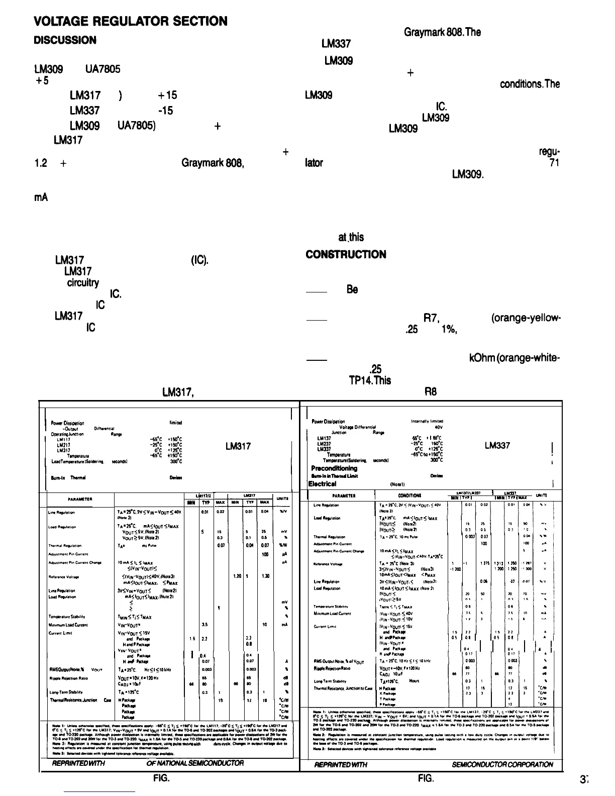
is adjustable from -1.2 to -37 Volts. It is used in the negative
variable supply of the
Graymark
808.The
specifications for
the
LM337
are shown in Fig. 70.
The 808 uses three voltage regulators as follows. The
LM309
and
UA7805
are interchangeable devices for the
+
5
VDC supply.
LM317
(Ul
)
for the
+
15
VDC supply
LM337
(U2) for the
-15
VDC supply
LM309
(or
UA7805)
(U3) for the
+
5 VDC supply
The
LM309
is a nonadjustable three terminal device, and
is used to regulate the
+
5 VDC supply so the output volt-
age is constant under varying load and line
conditionsThe
LM309
is an integrated circuit, and all of the circuitry to do
it’s job is contained within the
IC.
Current limiting is also in-
cluded in the design of the
LM309
to limit the output current
to safe value. The
LM309
also has internal thermal shut-
down protection circuitry to prevent it from overheating. If
the internal power dissipation becomes too great, the
regu-
later
will shutdown to prevent damage to itself. Figure
71
shows the specifications for the
LM309.
The
LM317
is a three terminal adjustable positive voltage
regulator. Refer to Fig. 69. Its output is adjustable from
+
1.2
to
+
37 Volts. As used in the
Graymark
808*
its output
is guaranteed to be adjustable upward to a minimum of a
regulated 15 Volts under worst case conditions, that is, 300
mA
output current and low input line voltage (95 Volts AC).
The output voltage is adjustable down to 0 Volts. This is
made possible by the design of the external control circuit-
ry. This will be discussed in the EXTERNAL CONTROL
AND PROTECTION CIRCUITRY section.
The three voltage regulators will be installed and tested one
at a time. Some of the associated circuit components have
already been installed so that tests could be performed,
and some of the voltage control components will be in-
stalled
at,this
time so that the regulators can be tested.
The
LM317
is an integrated circuit
(IC).
All of the circuitry
for the
LM317
to do it’s job, with the exception of the voltage
divider
circuitv
that controls the the output voltage, is con-
tained within the
IC.
Current limiting is also included in the
design of the
IC
to limit the output current to a safe value.
The
LM317
also has internal thermal shutdown circuitry to
prevent the
IC
from overheating. When the regulator reach-
es its maximum safe operating temperature, the regulator
will shutdown to prevent damage to itself by excessive
heating. All protection circuitry remains fully functional
even if the adjustment terminal becomes disconnected.
Refer to Fig. 72 for the following steps.
1.
Be
sure the 808 power plug is not connected to
a power outlet.
2. Mount resistor
R7,
340 Ohm
(orange-yellow-
black-black)
.25
Watt
l%,
on the PCB. Solder the
leads to the PCB and cut off any excess length.
3. Solder the leads of a 3.9
kOhm
(orange-white-
red)
.25
Watt test resistor to test pointsTP13 and
TPl4.This
resistor temporarily takes the place of
The LM337 is similar to the
LM317,
except that its output
variable resistor
R8
for test purposes.
,
1
I
Absolute Maximum Ratings
I
I
Absolute Maximum Ratings
Poww
Owlpatton
Input-Output
Voltag8
1
Power
D~ss~parton
internally
lrmited
1
Input
-Dutput
Voltage
Dtfferwwal
4ov
I
Operating
Junction
LMl37
Temperature
Operatmg
Junctton
Temperature
Range
-55Oc
to
+
1
WC
I
l_Mll?
-55Oc to
+150?
LM237
-25’C
to l
150’C
LW37
O’? to
+125’C
Storm
l*mpefatufo
-65Oc
IO
+15f.I”c
I
LM337
SPECIFICATIONS
!
Load
Temporotuw
6oldormg,
10
wcondsl
300OC
I
LM217
-25’C
to
+150’C
Lh4317
O’C
to
+I
25*C
LM317
Storage
Tomperarure
+5Oc
to
+
15fz1°C
SPECIFICATIONS
I
Lead
Temperature
~Solcfermg,
10
seconds)
300Oc
Preconditioning
Burdn
bn
lhomd
Limit
100% All
Dohom
1
Preconditioning
I
1
6urn-In
in
ThormaI
Limit
100% Ail
Devicas
1
Electrical Characteristics (Note 1)
1
Electrkal
Characteristics
(NOW
IJ
I
PARAMETER
I
CONDITIONS
LMlJ7/LMz37
I
LM337
MIN
1
TV?
1
MAX
1
MtN
1
TV?
1
UAX
UNITS
CONDITIONS
LW
1712
MfN
TYP
0.0t
5
0.1
003
50
0.2
1.20 1.25
0.02
m
0.3
1
35
15
2.2
0.5 0.8
LoWt
RJ6”tJtlo”
TA
=
25’C.
10
mA
5
IoUT
5
IMAK
\VOUTl
s
5V
INow
21
fVO,,T,
2
5V
INote
21
TA
-
25*C,
2V
5
Vffq
-
VDUT
5
40V
(Now
21
TA
=
25’C.
10
mA
5
IoUT
5
IMAX
V(,UT
5
5V.
(Note
21
VOUT
2
5V.
(Now
2)
TA
=
25°C. 20 ms
Pulse
OW?
007 0003
65
lal
65
I 5
1
t
225
-I
250
1275
1
?ll
1
250
-1200
-1250
1300
1200 t?50
007
005
0
07
007 0.04
007
UN
100 50
lC#l
MA
S
0.2 5 IJA
130
i.m
I
2s
130
V
0.05 0.02 0.07 WV
50 20 70
mV
t
03 15
?6
1
h
5 3.5
10
mA
15
22
A
05
0.8
A
10
mA
<
IL
5
tMAj(
2 5V
<
lVfN-VOuT,
<
40V.
TA
=
26’C
TA
*
26’C
WOtJ
31
3
5
!VlN-VOL,Tl
5
40V.
INotJ
31
t0
mA
5
~OLJT
<
tMAX
P
<
PMAX
LmJ
RJ6utJtmn
IV
<
IVlN-V@JT.
<
40V
INOte
21
2 5V
5
{VIN-Vt,UTj
5
40V
3
5
(VjN-VoUTJ
5
4OV.
(Note
31
10
mA
5
lou~
5
IMAX,
P
5
PMAX
Lw-w
RJgulJtaon
3V
5
VtN
-
VOUT
5
40V.
[Note
21
LoJd
RJ6ulJttw
10
mA
5
IOUT
5
IMAX,
(Note
2)
VOUT
5
5V
VOUT
2
5V
TJmpJrJturJ
StJb~htv
Mmumum
LoJd
CWWH
Cwww
LamIt
lMlN
5
TI
5
TMAX
VIN-VOUT
=
40V
V~N-VO~JT
5
t5V
K
JM,
T
Pdqe
bt
J”d
P
hdLJ$,J
I
VIN-
v(j(JT
=
40V
K
Jm-~d
T
PJckJ6J
I
I
0.4
I
Lo&
fbgulatmn
10
mA
5
lt,L,T
5
tMAX
INow
21
iVt,t,Tl
5 5V
sVt,L,Tl
2
5V
Mm1mum
Loti
c”rrwlt
IVIN-VOUTN
5
40V
!VlN-VC,t,Tl
5
t0V
I
IVIN-VO~JTI
5
15V
K
Jti
T
Pack*
I
H
Jt7d
P
Package
I
O5
I
O8
I I
O5
I
O6
I I
Ai
I
lVt~-VOUTI
* 40V
K J”d T PJchJtfJ
I
lo4
i
I
lo4
1
1
1
1
I
Id
J"d
“Package
tl
Jd
P
Package
RMS
Outout
Now,
%
of
I
Long.Twm
5tJbdw
TA
*
25’C.
10 Hz
5
f
5
IO
kl4z
VOUT
=
lOV,
t
-
120
HZ
CADJ
-
t&F
TA-
125’C
I
A
A
u
d0
d0
m
a,.aAd
Thermal
Rewstwtce,
Junetnxt
to
t&e
H
Pack-
12
1,
14 ID
cd,”
K
hckqje
23 3 2.3 3
-CM
T
hckaqa
4
*c/W
P
Pukqp
12
eClW
RMS
Outtwt
Now,
%
01
V(,uT
RIP@~
flqJa~on
RJUO
I
Vf,t,T
=
-10V.
f
-
120
HZ
CAOJ
l
t0uF
I
TA
=
125*C,
1000
HOW%
ThwmJl
RJWtJnC~.
.fuf!ctton
IO
CJsJ
1
HPackae
oula
mtma
with
J tow
dutv
CWJ.
REPRlmD
WI774
PERMISSION
bF
MTlONAL
SEMICONWCTOR
CORPORATION
REPRMED
WV?+
PERMISSION Of NATIONAL SEhflCOM?UCTOff
COf?POf?A77OiV
FIG.
69
FIG.
70

 Loading...