Repeat step 2 again, this time leaving the power
ON for
15
s.econds.
If none of the components heated up in the previ-
ous
steps1
power up the 808 again. Measure the
dc voltage between test points TP7 and TP17.
TP17 should be positive, and the voltage should
be between 12.7 and 15.8
Volts.The
reason that
a range of voltages is given is that the tolerances
of a number of components can affect the regula-
tor output voltage. If the voltage is not in this
range, check resistor
R7
and the 3.9
kOhm
resis-
tor installed temporarily between TP13 and
TP14. Make sure they are the correct resistors
for these locations. Consult with your instructor
if necessary.
Turn OFF the 808 power switch and remove the
power plug from the power outlet.
Mount 10
mF
capacitor C4 on the PCB, making
_
4
.
sure that the negative lead is inserted in the hole
marked
“J’.
Solder the capacitor leads to the PCB
and cut off any excess length.
5
.
Locate the positive variable voltage regulator, U 1
(LM317),
one of the small heat sinks, a 3 x 8mm
machine screw, a 3mm split lock washer and a
3mm hex nut.
Bend the three leads of the
LM317
regulator as
shown in Fig. 73. A long nose pliers is
agood
tool
to use for this.
Refer to Fig. 74. Mount the
LM317
regulator
and heat sink on the
l%B,
using the hardware
called out in step 5.
Graymark
recommends the
use of heat sink compound on the surfaces of
the voltage regulators and heat sinks where
they contact each other.
6
.
4
.
5
*
6
.
.
7
.
8
.
9
.
Before tightening the machine screw and nut that
holds the heat sink and regulator to the PCB,
ro-
tate the heat sink on the machine screw so that
its cooling fins are oriented as shown in Fig. 72.
Then tighten the machine screw and nut.
Solder the regulator leads to the PCB, using a
small alligator clip heat sink on each lead be-
tween the plastic regulator package and the top
surface of the PCB. Cut off any excess lead
length.
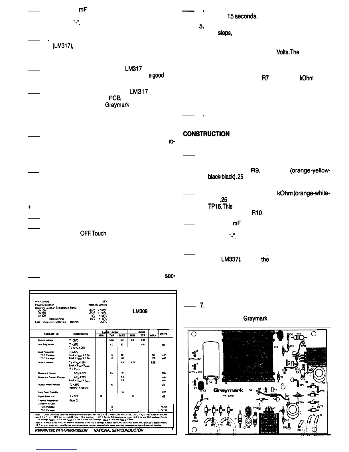
Refer to Fig. 72 for the following steps.
1. Be sure the 808 power plug is not connected to
a power outlet.
2. Mount resistor
R9,
340 Ohm
(orange-yellow-
blackblack)
.25
Watt 1%, on the PCB. Solder the
leads to the PCB and cut off any excess length.
3. Solder the leads of a 3.9
kOhm
(orange-white-
red)
.25
Watt test resistor to test pointsTP15 and
TPl6.This
resistor temporarily takes the place of
variable resistor
RlO
for test purposes.
+
15 VOLT REGULATOR TEST
1. Connect the 808 power plug to a power outlet.
2. Turn the 808 power switch ON, wait 1 second
and turn it
OFETouch
the components that were
installed in the construction steps that were just
completed. If any of these components are
warm, there is something wrong. Check the PCB
and components carefully, and consult with your
instructor if necessary.
4. Mount 10
mF
capacitor C5 on the PCB, making
sure that the negative lead is inserted in the hole
marked
“-“.
Solder the capacitor leads to the PCB
and cut off any excess length.
5. Locate the negative variable voltage regulator
(U2,
LM337),
one of
th&
small heat sinks, a 3 x
8mm machine screw, a 3mm split lock washer
and a 3mm hex nut.
3. Repeat step 2, leaving the power ON for 5
sec.
onds this time.
6. Bend the three leads of the LM337 regulator as
shown in Fig. 73. A long nose pliers is a good tool
to use for this.
7*
Refer to Fig 74. Mount the LM337 regulator and
heat sink on the PCB, using the hardware called
out in step 5.
Graymark
recommends the use of
Absolute Maximum Ratings
lvu~
VOllege
35v
poww
ow~oat~on
lntemali~
Lomated
Ooefatm9
Jwurwn
Temperature
Ran9e
LMlO9
-WC
to
+
15oY
IA209
-2sY
to
+
1
50°c
LM309
LM309
O’C
to
+
125OC
SPECIFICATIONS
Storage
Temperawe
Range
-65’C
to +150°C
head
lempratuw
Golciew19.
10
seconds)
Electrical Characteristics
300°C
T
T
15
15
5.2
40
15
2.5
u
MIN
47
4.6
50
,
-I-
V
mV
mV
mV
V
mA
mA
mA
PV
mV
d6
cofuomotus
1,
=
25T
1,
=2Pc,
7v
<
VW
<
25v
T,
=
25QC
SmA<lwT<O%
51?lA<lw,~15A
?V
<
VW
G
25v.
5mA
6
b,,,
6
I-.
P<P_
7v
<
VW
<
25v
7v
<
v*
fi
25v
5mAGl~Gl_
7.
=
25.T
1OHz
<
f
<
1tXIkHz
1,
=
25T
(NOW
2)
PARAMETER
MAX
5.2
50
50
100
5.25
10
0.5
0.0
20
REPRIUTED
WITH
PERMSSION
OF
M4TlONAL
SEMCONDUCTOR
CORPORATION
FIG. 71
FIG. 72
38

 Loading...