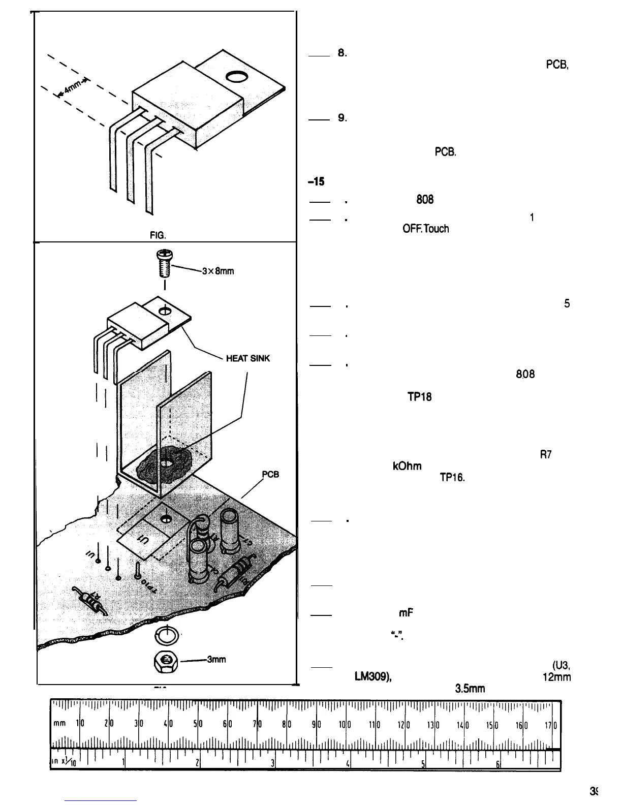
FIG.
73
!r
13
x
8mm
SCREW
I
COMPOUND
3mm SPLIT
/LOCK WASHER
Q
e
-3mm
NUT
FIG. 74
heat sink compound on the surfaces of the
voltage regulators and heat sinks where they
contact each other.
Before tightening the machine screw and nut that
holds the heat sink and regulator to the
PCB
rotate the heat sink on the machine screw so that
its cooling fins are oriented as shown in Fig. 72.
Then tighten the machine screw and nut.
Solder the regulator leads to the PCB, using a
small alligator clip heat sink on each lead
between the plastic regulator package and the
top surface of the
PCB.
Cut off any excess lead
length.
-15
VOLT REGULATOR TEST
1
.
2
.
3
.
4
.
5
.
6
.
Connect the
608
power plug to a power outlet.
Turn the 808 power switch ON, wait
1
second
and turn it
OFFTouch
the components that were
installed in the construction steps that were just
completed. If any of these components are
warm, there is something wrong. Check the PCB
and components carefully, and consult with your
instructor if necessary.
Repeat step 2, leaving the power ON for
5
seconds this time.
Repeat step 2 again, this time leaving the power
ON for 15 seconds.
If none of the components heated up in the
previous steps, power up the
8.06
again.
Measure the dc voltage between test pointsTP7
and TP18.
TPl8
should be negative, and the
voltage should be between 12.7 and 15.8 Volts.
The reason that a range of voltages is given is
that the tolerances of a number of components
can affect the regulator output voltage. If the
voltage is not in this range, check resistor
R7
and
the 3.9
kOhm
resistor installed temporarily
betweenTP15 and TPl6. Make sure they are the
correct resistors for these locations. Consult with
your instructor if necessary.
Turn OFF the 808 power switch and remove the
power plug from the power outlet.
CONSTRUCTION
Refer to Fig. 72 for the following steps.
1. Be sure the 808 power plug is not connected to
a power outlet.
2. Mount 10
mF
capacitor C6 on the PCB, making
sure that the negative lead is inserted in the hole
marked
“-‘I
Solder the capacitor leads to the PCB
and cut off any excess length.
3. Locate the positive fixed voltage regulator
(U3,
LM309),
the large heat sink, two 3.5 x
12mm
machine screws, two
3.5mm
split lock washers
3(
.

 Loading...