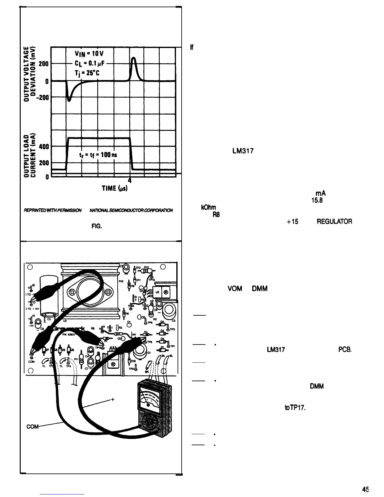
LOAD TRANSIENT RESPONSE
0
1
2
3
4
5
6
TwiE
bd
EPm/7Ell
WIW
PEaMss~uN
OF
u4mNAL
sEM/coNmJcmR
coRPoRAnoN
FIG.
82
FIG.
83
voltage, along with the output current and voltage, affect
the amount of power that the regulator has to dissipate.The
size of the heat sink and the amount air flow around it
affects how much the temperature of the regulator must
rise to dissipate this power.
If
a voltage regulator gets too hot, it will be damaged, even
though the current flowing through it is within safe limits.
The protection circuitry on the voltage regulator chip
includes a temperature sensor. When the chip temperature
reaches its maximum safe limit, the protection circuitry
begins to divert some of the op amp output current from the
Darlington transistor base, just as it did when the regulator
output current reached its maximum safe value, as we
discussed earlier.
OVER TEMPERATURE PROTECTION
DISCUSSION
To force the
LM317
voltage regulator into its over
temperature protection mode without risking damage to
other power supply components, the regulator will be
operated without a heat sink attached while supplying
approximately the maximum rated current of the power
supply. The 50 Ohm 5 Watt test resistor that will be used
for a load draws between 254 and 316
mA
with the
regulator output voltage between 12.7 and
15.8
Volts. The
3.9
kOhm
test resistor that was installed in place of variable
resistor
R8
sets the regulator output within this range. If you
wish to, refer back to step 5 of the
+
15
VOLT
REGUMTOR
TEST
TEMPERATURE PROTECTION EXPERIENCE
Purpose: To observe a voltage regulator and its output
when if is in the over temperature protection mode.
Equipment: Oscilloscope
VOM
or
DMM
50 Ohm 5 Watt Test Resistor
Drinking Straw
1. Be sure that the 808 power plug is NOT
connected to a power outlet.
Refer to Fig. 84 for the following steps.
2
.
3
.
4
.
5
.
6
.
Temporarily remove the mounting hardware and
heat sink for the
LM317
regulator from the
PCB*
Solder the 50 Ohm test resistor leads toTP7 and
TPl7.
Connect the ground lead of the scope and the
negative lead of the DVM or the
DMM
to the test
resistor lead going to TP7. Connect the scope
probe and the positive lead of the meter to the
test resistor lead going toTPl7. Adjust the meter
and scope to read and display a 15 Volt DC
signal.
Connect the 808 power plug to a power outlet.
Turn the 808 power switch ON. Watch the meter
and scope display. Depending on the ambient
temperature and the power line voltage, it may
take a minute or more for the voltage regulator to
reach the temperature at which the over

 Loading...