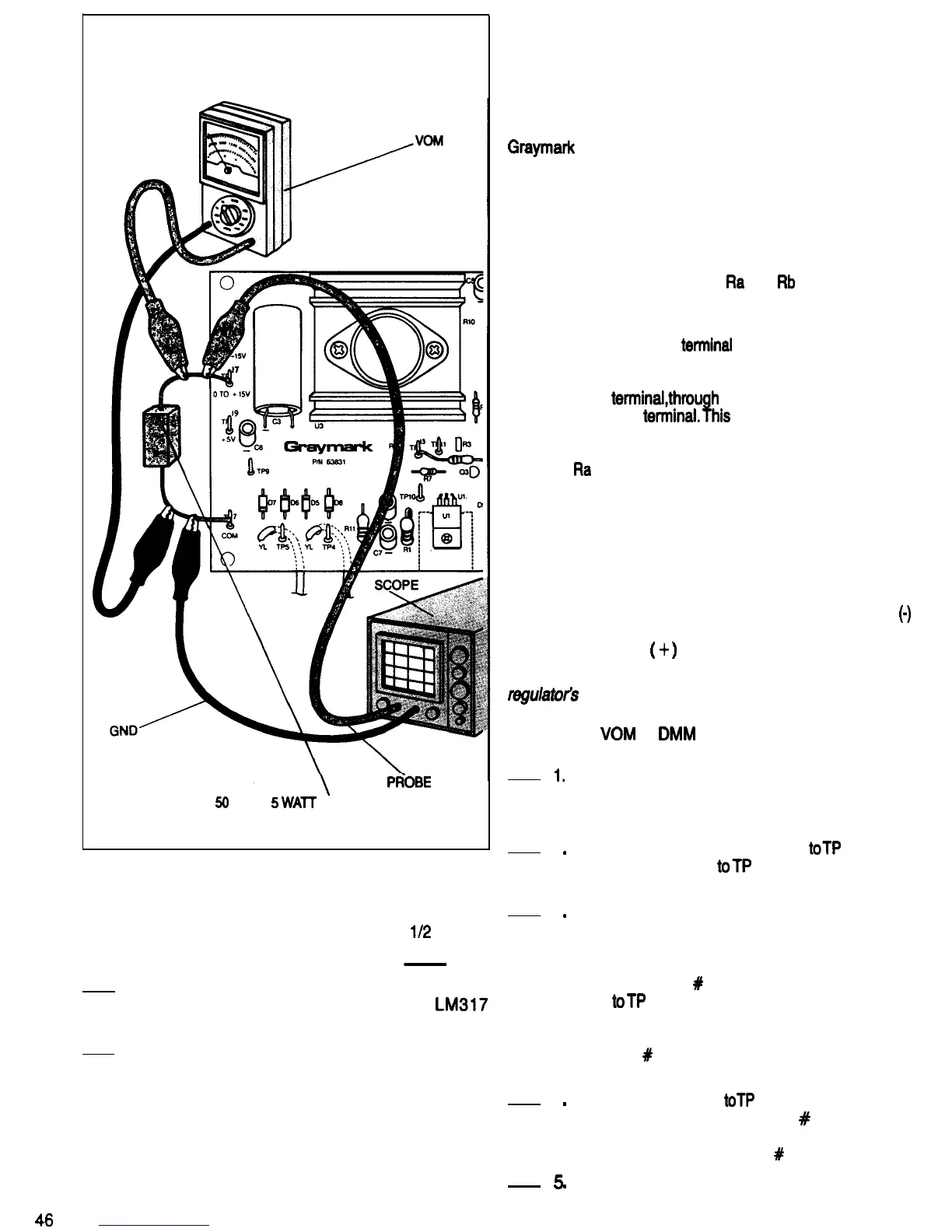
PtiOBE
50
OHM
5
WAT
T&T
RESISTOR
FIG. 84
temperature protection circuitry begins to
operate. When the over temperature circuit is
activated, the voltage across the test resistor will
begin to drop. Wait approximately
1/2
minute
longer. What is the meter reading?
-
Volts
7.
While watching the meter and scope display, use
the drinking straw to blow on the
LM3l7
regulator. What happens?
8. Turn OFF the 808 power switch and remove the
power plug from the power outlet. Disconnect the
test equipment and unsolder the test resistor.
Replace the heat sink and mounting hardware
that was removed in step 2.
This completes the TEMPERATURE PROTECTION
EXPERIENCE. Have your instructor initial your progress
chart.
46
EXTERNAL CONTROL AND PROTECTION
CIRCUITRY SECTION
VOLTAGE CONTROL
DISCUSSION
Figure 85 is a partial block diagram and schematic of the
Graymark
808 Power Supply, with the external voltage
control circuitry highlighted.
Figure 86 is a functional diagram of the positive adjustable
regulator and its external voltage control circuitry. The
negative adjustable regulator is similar, but with reversed
voltage polarities. Comparing this schematic with the
functional schematic of the fixed voltage regulator shown
in Fig. 80, we see that resistors
Ra
and
Rb
are now outside
the regulator, and that the ground terminal has become the
adjustment terminal.
Because the adjustment
terminal
Is the control Input of the
voltage regulator, the current necessary to operate the op
amp and protection circuitry inside the regulator must flow
from the input
terminal,through
the regulator circuitry and
through the output
terminal.This
is why there needs to be
some output current flowing whenever the regulator is
operating. The bleeder resistor and the voltage control
resistors,
Ra
and Rb, provide the load needed to cause this
current flow.
ADJUSTMENT VOLTAGE EXPERIENCE
The voltage that is applied to the adjustment terminal of a
voltage regulator determines the output voltage of that
regulator. The op amp inside the regulator adjusts the
resistance of the Darlington transistor so that the voltage
at the op amp’s inverting input (marked with a minus
(0)
sign) is the same as the voltage at its non-inverting input
(marked with a plus
(
+
)
sign).
Purpose: To demonstrate how an adjustable voltage
regulator3
output responds to different voltages at the
adjustment terminal.
Equipment:
VOM
or
DMM
Clip Lead
1.
Be sure the 808 power plug is not connected to
a power outlet.
Refer to Fig. 87 for the following steps.
2
.
3
.
4
.
5
.
Connect the negative meter lead
toTP
7 and the
positive meter lead
toTP
17. Set the meter to a
range that will read up to 20 Volts DC.
Connect the 808 power plug to an outlet and turn
the power switch ON. Write the voltmeter reading
down in Fig. 88 in the “Output Voltage” column
and the Clip Lead Connections “None” row (in
the box marked
#
1). Move the negative meter
lead
toTP
13 and write the voltmeter reading in
the “Output to Adjustment Voltage Difference”
column and the Clip Lead Connections “None”
row (box
#
2). Set the meter range selector to a
lower range if necessary for an accurate reading.
Connect the clip lead
toTP
13 and TP 2. Write the
meter reading down in box
#
3. Move the
negative meter lead back to TP 7 and write the
meter reading down in box
#
4.
Disconnect the negative meter lead from TP 7

 Loading...