RI
TPIC?
-
FIG.
85
INPUT
DARLINGTON
TRANSISTOR
r
~~~~~.
7
4 VOLTS
UNREGUlATED
l-
I
6
ADJUSTMENT
COMMON
t
-24
VOLTS
I
UNREGULATED
FIG. 86
FIG. 87
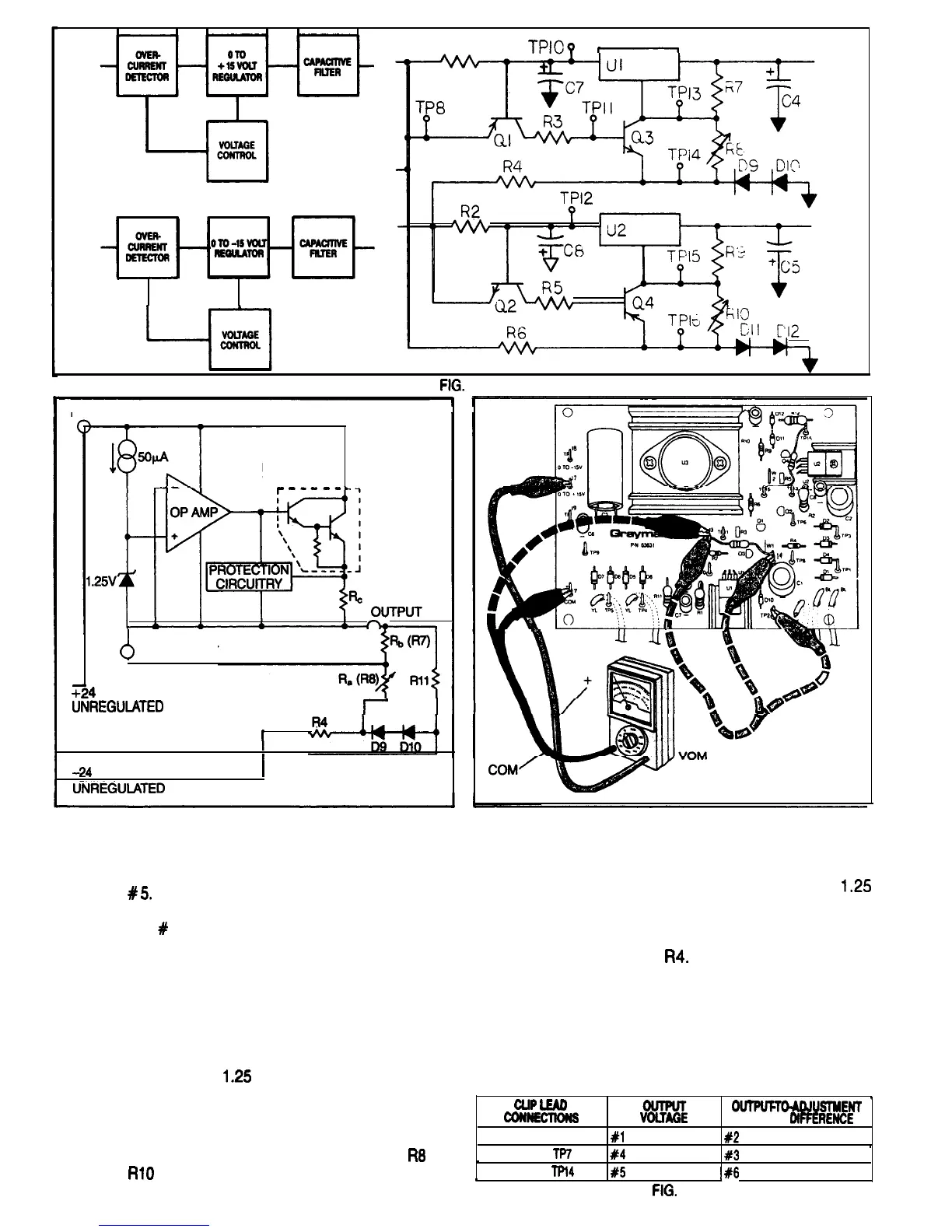
while you change one end of the clip lead from
TP 2 to TP 14. Reconnect the negative meter
lead to TP 7 and write the meter reading in box
#
5.
Move the the negative meter lead from TP
7 to TP 13 and write down the meter reading in
box
#
6.
Notice that while the output voltage changed
when the adjustment terminal of the voltage
regulator was connected to different voltages,
the output-to-adjustment voltage difference
remained the same.The op amp was controlling
the Darlington transistor resistance so that the
op amp’s input terminals remained at the same
voltage- The
1.25
Volts across the output and
regulator output voltages.
When the adjustment terminal is connected to
ground, the regulator output voltage is
1.25
Volts. To be able to adjust the output voltage to
0 Volts, two diodes connected in series are
forward biased by the unregulated negative
supply, through
R4.
The exact voltage drop
across the diodes will vary with the current
flowing through them and their temperature, but
it is approximately 1.4 Volts, or 0.7 Volts for each
diode.This results in the variables supplies being
adjustable to and a little beyond zero Volts. With
the voltage controls turned all the way down, the
adjustment terminals of the regulator is actually
,
the voltage of the voltage reference inside the
CLIP
LEA0
regulator.
WNNKTDNS
OUTPUFTM&JUSTMENT
VOlTAGE
VOLTAGE
DIFFERENCE
NONE
.
#l
#2
,
Later, when you connect potentiometers
R8
and
TP13 TO
TP?
#
#4
#3
.
RlO
to the PCB, they will control the adjustable
TP13 TO
Tfl4
#5
,
k#6
FIG.
88
47
 Loading...