EasyManua.ls Logo

GREAT PLAINS 1206NT - User Manual

GREAT PLAINS 1206NT
30 pages
Print Icon
To Next Page IconTo Next Page
Loading...
Manufacturing, Inc.
www.greatplainsmfg.com
© Copyright 2017 Printed 12/03/2020 150-166Q
EN
Table of Contents
Table of Contents
ORIGINAL INSTRUCTIONS
Pre-Delivery Instructions
1206NT
End-Wheel, No-Till Drill
Read this manual entirely. When you see this symbol, the subsequent
instructions and warnings are serious - follow without exception.
Your life and the lives of others depend on it!
Illustrations may show optional equipment not supplied with standard unit.
EN
Question and Answer IconNeed help?

Do you have a question about the GREAT PLAINS 1206NT and is the answer not in the manual?

Summary

Important Safety Information

Safety Symbols and Signal Words

Explains safety alert symbols and signal words (DANGER, WARNING, CAUTION) for hazard recognition.

Emergency Preparedness and Decals

Guidance on emergency readiness and the importance of safety decals.

Operational Safety Guidelines

Protective Equipment and Fluid Hazards

Advises on protective gear and warns about high-pressure fluid leaks.

Chemical Handling Safety

Instructions for safe handling, use, and disposal of chemicals.

Transport and Storage Safety

Rider, Visibility, and Transport Safety

Covers safety for riders, visibility, and safe transport of machinery.

Equipment Handling Safety

Shutdown, Storage, and Tire Safety

Details procedures for shutdown, storage, and safe tire maintenance.

Safe Maintenance Practices

Offers general guidelines for performing maintenance tasks safely.

General Operating Safety

Safety Awareness and Decals

Emphasizes continuous vigilance, operational understanding, and decal maintenance.

Introduction

Unit Description and Models

Description of the 1206NT drill and list of covered models.

Manual Usage and Assistance

Manual Guidance and Definitions

Guides on manual usage and defines key terms.

Further Assistance Contact

Provides contact information for obtaining additional support and assistance.

Preparation and Tools

Assembly and Setup Overview

Outlines the general sequence of assembly and setup tasks for the drill.

Tools and Assistance Information

Specifies necessary tools and provides information for obtaining further assistance.

Unloading the Truck

Assembly Process

Pre-Assembly Checklist

A comprehensive checklist to ensure all prerequisites for assembly are met.

Tools Required for Assembly

Lists the tools necessary for the assembly process.

Tongue Assembly

Removing and Preparing the Tongue

Instructions for removing and preparing the drill's tongue component.

Installing the Tongue

Mainframe Tongue Installation

Detailed procedure for installing the drill's tongue onto the mainframe.

Lighting and Hose Routing

Lighting Installation

Guidance on installing lighting components and routing hydraulic hoses.

Harness and Hose Connections

Instructions for routing and connecting lighting harnesses and hydraulic hoses.

Hydraulic Hose Routing Details

Hydraulic Hose and Harness Routing

Further instructions on routing and securing hydraulic hoses and lighting harnesses.

Setup: Hitching and Options

Optional Features and Hitching Safety

Advises on optional features and provides critical hitching safety warnings.

Clevis Hitch Assembly

Step-by-step instructions for assembling the clevis hitch component.

Hitch Height Adjustment

Hitch Height Configurations

Illustrates and explains various hitch height adjustments for optimal operation.

Hitch Adjustment and Safety Chain

Adjusting Clevis and Pintle Hitches

Details the process for adjusting both clevis and pintle hitch configurations.

Safety Chain Installation

Provides instructions for securely installing the safety chain.

Equipment Handling and Hydraulics

Jack Storage

Instructions on properly storing the drill's jack.

Hydraulic Hookup and Flow Setting

Hydraulic Connector Usage

Explains the proper procedure for connecting hydraulic hoses to the tractor.

Transport Lift Cylinder Flow Setting

Details how to set the flow control for transport lift cylinders.

Hydraulic System Bleeding

Bleeding Air from Hydraulics

Step-by-step guide for bleeding air from the drill's hydraulic system.

Cylinder Rephasing and Leveling

Rephasing Hydraulic Cylinders

Explains how to rephase hydraulic cylinders to ensure level operation.

Leveling the Drill

Provides instructions for leveling the drill using the hydraulic cylinders.

Appendix: Torque and Tire Specs

Tire Size and Pressure

Specifies the correct tire size and recommended inflation pressure.

Torque Values Chart

A chart listing torque values for various bolt sizes and grades.

Hydraulic Connector Specifications

Hydraulic Connectors and Torque

Details different types of hydraulic connectors and their torque specifications.

Overview

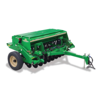
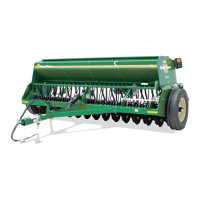
The document provided is a Pre-Delivery Instructions manual for the Great Plains 1206NT End-Wheel, No-Till Drill. This manual outlines the assembly, setup, and initial maintenance procedures for the machine before it is delivered to a customer.

Function Description

The Great Plains 1206NT No-Till Drill is a 12-foot grain drill designed for no-till farming operations. Its primary function is to precisely plant seeds without prior tillage, minimizing soil disturbance. The drill features an end-wheel design, which helps maintain consistent ground-working component alignment with the end wheels. This design ensures accurate coulter depth and seed placement, even when operating on uneven terrain or following field curves, by preventing side-loading of the openers.

Important Technical Specifications

The manual lists several models of the 1206NT drill, all of which are 12-foot end-wheel no-till drills with varying inch measurements:

  • 1206NT-1410: End Wheel No-Till 12 ft. 10 in.
  • 1206NT-1808: End Wheel No-Till 12 ft. 8 in.
  • 1206NT-1975: End Wheel No-Till 12 ft. 7-1/2 in.
  • 1206NT-2007: End Wheel No-Till 12 ft. 7 in.

Lifting Capacity:

  • A lift or overhead hoist with a minimum lifting capacity of 8000 pounds (3628 kg) is required for assembly.

Hydraulic System:

  • The drill's hydraulic system has a capacity of approximately 1 gallon of fluid.
  • The transport lift cylinders require a flow setting of no more than 9 gpm (34.07 lpm) at the tractor.
  • The hydraulic system uses rephasing cylinders, which require specific bleeding procedures to function correctly.

Tire Specifications:

  • Tire size: 295/75/R x 22.5"
  • Recommended tire pressure: 65 psi (4.5 bar)

Torque Values: The manual provides a comprehensive "Torque Values Chart" for various bolt sizes and grades (Grade 2, Grade 5, Grade 8 for imperial; Class 5.8, Class 8.8, Class 10.9 for metric). Torque tolerance is specified as +0%, -15% of the listed values.

  • Imperial Bolts:
    • 1/4-20 (Grade 2): 5.6 ft-lb (7.4 N-m)
    • 1/4-20 (Grade 5): 8 ft-lb (11 N-m)
    • 1/4-20 (Grade 8): 12 ft-lb (16 N-m)
    • ...up to...
    • 1-1/2-12 (Grade 8): 3560 ft-lb (4820 N-m)
  • Metric Bolts:
    • M5 X 0.8 (Class 5.8): 3 ft-lb (4 N-m)
    • M5 X 0.8 (Class 8.8): 5 ft-lb (6 N-m)
    • M5 X 0.8 (Class 10.9): 7 ft-lb (9 N-m)
    • ...up to...
    • M36 X 2 (Class 10.9): 3220 ft-lb (4100 N-m)

Hitch Heights (Tongue Level in Field Position): The manual provides a chart for ideal hitch heights for both Clevis and Pintle hitches, with the tongue level in field position. These measurements vary depending on the specific hitch configuration and are crucial for optimal drill performance. For example, a Clevis hitch can have heights ranging from 14 in (35.6 cm) to 24.0 in (61.0 cm), and a Pintle hitch from 13.5 in (34.3 cm) to 23.5 in (59.7 cm). When level, the top of the tongue tube should be approximately 26 3/4 in. (68cm) above the ground at the hitch.

Usage Features

The manual focuses on pre-delivery assembly and setup, which are critical for the drill's proper operation.

  • Assembly Sequence: The general sequence involves unloading the frame, tongue, and accessories, assembling the tongue to the mainframe, and routing hoses and harnesses.
  • Setup Sequence: This includes adjusting hitch height, hitching to the tractor, leveling the drill, bleeding hydraulics, installing accessories/options, and setting coulter depth control.
  • Folding Tongue: The drill features a folding tongue design, which requires specific steps for unfolding and securing it with bolts, lock washers, nuts, and a locking pin.
  • Hitching to Tractor: Detailed instructions are provided for connecting the drill to a tractor, including adjusting the clevis or pintle hitch height to ensure the tongue is level in the field position.
  • Hydraulic Hookup: The hydraulic hoses are color-coded with handle grips (e.g., Blue for Transport Lift Cylinders, Orange for Marker Cylinders) and symbols to ensure correct connection to the tractor's remote outlets. Hoses with an extended-cylinder symbol feed cylinder base ends, while retracted-cylinder symbols feed cylinder rod ends.
  • Safety Chain: Instructions emphasize connecting the safety chain around a suitable anchor on the tractor, ensuring enough slack for turning but preventing it from touching the ground.
  • Jack Storage: The jack can be retracted and stored on a mounting tube on top of the tongue.

Maintenance Features (Pre-Delivery Focus)

While primarily a pre-delivery manual, it includes initial maintenance and checks:

  • Pre-Assembly Checklist: Before assembly, users must read safety information, ensure at least two people are present, work in a level and clear area, confirm all major components and fasteners are present, and have the parts manual handy.
  • Inspection: Check that all working parts move freely, bolts are tight, and cotter pins are spread. Verify proper tension and alignment on all drive chains.
  • Decal and Reflector Check: Ensure all safety decals and reflectors are correctly located, legible, and replaced if damaged.
  • Tire Inflation: Inflate tires to the recommended pressure (65 psi / 4.5 bar) and tighten wheel bolts to specified torque values.
  • Hydraulic Bleeding: A critical pre-delivery maintenance step is bleeding air from the rephasing hydraulic cylinders. This involves checking fluid levels, supporting the drill, unpinning and raising cylinders, extending and retracting cylinders multiple times with the tractor engine idling, and finally pinning the cylinders back in place. This process ensures smooth and even lifting of the drill.
  • Rephasing Cylinders: If cylinders get out of phase (one side too low or high), the drill must be raised completely, and the tractor hydraulic lever held for a few seconds to allow rephasing.
  • Leveling Drill: After bleeding, the drill must be leveled by adjusting cylinder eyebolts to achieve approximately 3 1/16 inches of threads above the mounting plate, raising the drill 1-2 inches off the ground, measuring coulter tube height, and adjusting eyebolts until the drill is level, then tightening the nuts.
  • Hydraulic Connector Torque: Specific torque values are provided for different types of hydraulic fittings (NPT, JIC, ORB) to ensure secure and leak-free connections. For NPT fittings, liquid pipe sealant is recommended. For JIC and ORB fittings, no sealants are used, but ORB O-rings should be lubricated with clean hydraulic fluid.

GREAT PLAINS 1206NT Specifications

General IconGeneral
BrandGREAT PLAINS
Model1206NT
CategoryDrill
LanguageEnglish

Related product manuals