24
beams. Position the engine on the mount so that the drive
washer is 7-1/4" [184mm] from the fi rewall. Clamp the
engine in this position. Drill and tap your engine mount using
an 8-32 tap set. Install the engine to the mount using four
8-32 x 1" [25mm] socket head cap screws (SHCS), four #8
lock washers, and four #8 washers.
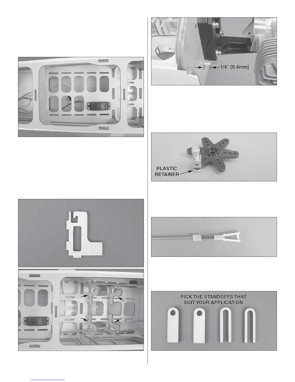
❏ 6. Install the throttle servo in the center equipment tray as
shown. Use a 1/16" [1.6mm] drill bit for the servo screw holes.
❏ 7. Dry-fi t the fuel tank supports and route the plastic outer
pushrod tube from the fi rewall to the servo.
❏ 8. Trim the plastic pushrod tube so that there is at least 1/4"
[6.4mm] of tube protruding forward of the fi rewall and that
there is approximately 1-1/2" [38mm] of distance between
the throttle servo output shaft and the tube. When you’re
satisfi ed with the fi t of the pushrod tube, epoxy the fuel tank
supports in place. Roughen the outer surface of the pushrod
tube and epoxy it in place.
❏ 9. Install a screw-lock pushrod connector onto a short
servo arm. Use a plastic retainer to hold this to the servo
arm and a 4-40 x 1/4" [6.4mm] SHCS. Turn on your radio and
position the servo arm. Install the arm to your throttle servo
using the servo screw supplied with your servos.
❏ 10. Locate the 2-56 x 36" [914mm] threaded one-end rod,
one plastic clevis, and one silicone clevis retainer. Thread
the plastic clevis onto the rod so that at least 3/8" [10mm] of
thread is engaged. Slide a silicone retainer onto the rod and
fi t it into the pushrod tube.
❏ 11. Locate two throttle rod standoffs. You will use these
to support the pushrod tube at the servo arm, so slide these