Do you have a question about the GReddy e-manage ultimate and is the answer not in the manual?
Key product usage guidelines and restrictions, including legality and system compatibility.
Critical safety precautions for installation and operation, emphasizing trained personnel and safe tuning environments.
Precautions regarding tuning, garage ventilation, handling flammable substances, and avoiding driver interference.
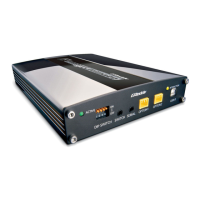
Explanation of the unit's active status LED states and their meanings.
Explanation of the unit's interaction status LED states for communication.
Description of DIP SWITCH, SERIAL, OPTION ports, and USB-B connection.
Details on connecting the main harness to the unit.
Detailed guide on setting and locating jumpers for vehicle sensors and application maps.
Essential steps, tools, and cautions before commencing installation.
Step-by-step guide for properly splicing electrical wires.
Instructions for correctly installing electrical connectors onto wires.
Diagram of ECU connectors A, B, and C with signal descriptions.
Diagrams for various airflow meters, throttle, and RPM signals.
Specific wiring for RB26DETT engines with dual airflow meters.
Diagrams for connecting VTEC output and input signals.
Instructions for wiring the idle control valve pulse input.
Explanation of jumper settings and diagrams for 6-cylinder injector wiring.
Procedures for changing injection timing and wiring sub-injectors.
Chart correlating engine firing order with e-manage ignition channels.
Diagrams for distributor and direct ignition systems, including channel conversion.
Usage of analog channels for boost limiters and sensor inputs.
Connecting for speed cut elimination and data logging.
Connecting crank/cam signals for RPM recognition and data logging.
Wiring for water/intake temp and knock sensors for monitoring and relay activation.
Connecting to the Nissan Valve Control System solenoid.
Using channels to activate external relays for devices.
Visual representation of ECU locations within a vehicle's cabin.
Reference chart for all signal symbols used in wiring diagrams.
Detailed ECU connector pin assignments for Toyota and Lexus models.
Detailed ECU connector pin assignments for Nissan and Infiniti models.
Detailed ECU connector pin assignments for Honda and Acura models.
Detailed ECU connector pin assignments for Mitsubishi models.
Detailed ECU connector pin assignments for Mazda models.
Detailed ECU connector pin assignments for Subaru models.
| Type | Piggyback ECU |
|---|---|
| Software | E-manage Ultimate Software |
| Operating Voltage | 12V |
| Application | Tuning and managing engine performance |
| Fuel Control | Yes |
| Ignition Control | Yes |
| Boost Control | Yes |
| Data Logging | Yes |
| Communication | USB |
| Ignition Timing Adjustment | Yes |
| Fuel Injection Adjustment | Yes |
| Compatible Sensors | MAP, TPS |
| Software Interface | Windows-based software for tuning and data logging |
| Tuning Modes | Real-time tuning, map-based adjustment |
| Features | Anti-lag, launch control |
| Input Channels | 8 analog inputs, 4 frequency inputs, 4 switch inputs |
| Output Channels | 8 outputs (injector, ignition, solenoid, etc.) |