5
Unit Installation
7
8
6
35
36
34
X17
X18
CN26
CN27
2T1
4T26 T3
1L1
3L2
5L3
13
NO
21
NC
A1
14
NO
22
NC
A2
2T1
4T26 T3
1L1
3L2
5L3
13
NO
21
NC
A1
14
NO
22
NC
A2
XT2
7
8
6
34
35
36
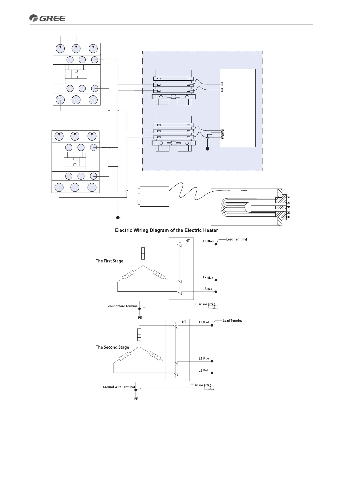
Electric Box
Wiring Board
AC Contactor 1
AC Contactor 2
Tank-type Electric Heater
Main Board AP1
Thermostat
Sensing probe
Neutral Line
Field Installation Diagramof the Electric Heater
(with the thermostat)
(2) See the following statement for installation of two groups of auxiliary electric heaters, including wiring of
the AC contactors and the tank-type electric heater.
◆
Wiring of the AC contactors is the same as that stated above.
◆
When the thermostat is not required, do the wiring as shown in the diagram below. The output terminal
used to control the thermostat should be short-circuited and then be connected to terminal 9 ( it is the
terminal for the neutral line).
 Loading...