Do you have a question about the Gree ETAC2-07HC230VA-A and is the answer not in the manual?
Diagrams illustrating electrical connections and components for different unit models.
Explanation of remote controller buttons, icon displays, and basic operation.
Details on control panel buttons, their functions, and status indicators.
Detailed explanation of system functions in cooling, dry, fan, and heating modes.
Important safety warnings and guidelines for installation and maintenance.
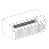
Instructions for installing the unit chassis, including retrofit applications.
List of error codes, their A/C status, and possible causes for malfunctions.
Troubleshooting guide for common air conditioner malfunctions and their causes.
Step-by-step methods for resolving common operational issues and malfunctions.
Exploded view diagram and parts list for cooling, heat pump, and auxiliary electric heater units.
Steps to remove the front panel and filter of the air conditioning unit.
| Brand | Gree |
|---|---|
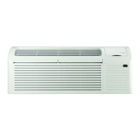
| Model | ETAC2-07HC230VA-A |
| Category | Air Conditioner |
| Language | English |