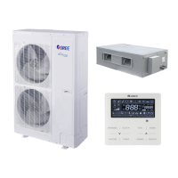
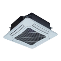
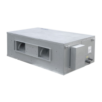
Ducted Type Split Air-Conditioner Units(Inverter Series)
25
4.2.2.2 Debugging Process
Debugging procedure for test run, display instruction for indicator on main
board of outdoor unit and operation method are as below:
Description of each stage of debugging progress
Instruction for Code and Operating Method
Progress
LED
Display code
Display
status
Start A0 Always ON
No debugged yeat. Press “SW3” button consecutively in the
master module for over 5s to enter auto debugging.
01_Master unit
setting
01/CC
Display
repeatedly
The system has no master unit.
Debugging can’t be continued, all buttons are invalid,
disconnect the power to reset the correct “SA6” DIP.
01/CF
Display
repeatedly
The system has two or more master units.
Debugging can’t be continued, all buttons are invalid,
disconnect the power to reset the correct “SA6” DIP.
01/oC
Display
repeatedly
The system has only one master unit.
After displaying once circularly, the system will enter the next
step automatically.
02_Address
allocation
02 Bllink The system is allocating address, which might takes 10s.
02/L7
Display
repeatedly
No master indoor unit.
It will display for 1min continuously. The user can set master
through debugging the software within 1min. If no master unit
is set manually within 1min, the system will set the indoor unit
with the smallest IP address automatically as the master
02/oC
Display
repeatedly
Address allocation of the system is complete with master
indoor unit.
After displaying once circularly, the system will enter the next
03_ Confirm
quantity of
outdoor units
03/ quantity of
modules in the
system
Display
repeatedly
Confirmation of quantity of modules in the system.
To differentiate from the debugging step, the QTY of module
will display only 1-digit on the right.
03/oC
Display
repeatedly
After 10S, all the nixie tubes of modules will display “03” and
“oC”, after displaying once circularly, the system will enter the
next step automatically.
 Loading...