EasyManua.ls Logo

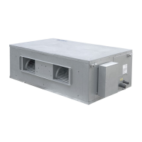
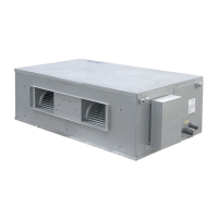
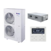
Gree FGR20Pd/DNa-X User Manual

Gree FGR20Pd/DNa-X
41 pages
To Next Page IconTo Next Page
Page #1 background imageLoading...
Page #1 background image
Owner's Manual
Original Instructions
Commercial Air Conditioners
Ducted Type Split Air-Conditioner Units(Inverter
Series)
Models:
FGR20Pd/DNa-X
FGR25Pd/DNa-X
FGR30Pd/DNa-X
FGR40Pd/D(2)Na-X

Other manuals for Gree FGR20Pd/DNa-X

Questions and Answers:

Gree FGR20Pd/DNa-X Specifications

General IconGeneral
BrandGree
ModelFGR20Pd/DNa-X
CategoryAir Conditioner
LanguageEnglish

Summary

1 Safety Precautions

1.1 Safety Notices

Important warnings and prohibitions regarding unit operation and user safety.

1.2 Power Supply Demand

Requirements for electrical power supply, wiring, and grounding for safe operation.

2 Installation of Indoor Unit

2.1 Selection Proper Installation Location

Guidelines for choosing the optimal location for the indoor unit installation.

2.2 Outline Dimension and Installation Spots

Physical dimensions and recommended installation spots for the indoor unit.

2.3 Drainage Pipe Installation and Drainage System Testing

2.3.1 Notice for Installation of Drain Pipe

Key considerations and precautions for the proper installation of the drain pipe.

2.3.2 Drainage Pipe Installation

Detailed steps and methods for installing the drainage pipe correctly.

2.3.3 Test of Drainage System

Procedures for conducting a test of the drainage system to ensure it functions correctly.

2.4 Installation of Air Duct

2.4.1 Installation of Air-out Duct

Specific instructions and guidelines for installing the air-out duct.

2.5 Indoor unit static pressure notch adjustment

2.6 Installation of Wired Controller

2.7 Wiring Work

2.7.1 Connection of Wire and Patch Board Terminal

Detailed steps for connecting wires to the patch board terminal.

2.7.2 Connect Communication Wire of Wired Controller

Instructions on how to connect the communication wire for the wired controller.

2.7.3 Illuminate for Connection of Wired Controller and Indoor Units Network

Information on connecting wired controllers within the indoor unit network.

3 Installation of Outdoor Unit

3.1 Dimension of Outdoor Unit and Mounting Hole

Physical dimensions and mounting hole specifications for the outdoor unit.

3.2 Installation Space Requirement

Required clearances and space specifications for the outdoor unit installation.

3.3 Refrigerant Pipe Connection

Guidelines, principles, and permitted values for connecting refrigerant pipes.

3.4 Vacuum Pumping, Refrigerant Adding

3.4.1 Vacuum Pumping

Procedure for vacuum pumping the indoor unit and connection pipes.

3.4.2 Refrigerant Adding

Steps and considerations for adding refrigerant to the system.

3.5 Electric Wiring

3.5.1 Notices for Wiring

Crucial notices and requirements for performing electrical wiring safely and correctly.

3.5.2 Wiring Diagram

Diagram illustrating the wiring connections between outdoor, indoor units, and wired controller.

3.5.2 Wiring Diagram

Wiring diagrams and specifications for circuit breakers and power cords for different models.

4 Check Items after Installation and Test Operation

4.1 Check Items after Installation

Checklist of critical items to verify after the installation is completed.

4.2 Test Operation and Debugging

4.2.1 Prepare The Test Operation and Debugging

Steps and precautions to take before performing test operation and debugging.

4.2.2 Test Operation and Debugging

Detailed procedure for performing test operation and debugging of the unit.

4.2.2 Test Operation and Debugging

Explanation of buttons and display tubes on the motherboard for unit control and configuration.

4.2.2.1 Basic Operation of Project Debugging

Steps for initiating, managing, and completing project debugging sessions.

4.2.2.2 Debugging Process

4.2.2.2 Debugging Process

Debugging stages for confirming indoor unit quantity and detecting outdoor unit components.

4.2.2.2 Debugging Process

Debugging stages for component inspection, compressor preheating, and valve status confirmation.

5 Common Malfunctions and Troubleshooting

Unit Doesn't Work

Troubleshooting steps when the unit fails to start or operate.

Unit Runs But Stops Immediately

Diagnosing and resolving issues where the unit stops unexpectedly after starting.

Abnormal Cooling or Heating

Addressing problems related to inefficient or incorrect cooling and heating performance.

Following Circumstances Are Not Malfunctions

Identification of normal operating conditions that may appear as malfunctions.

6 Error Indication

Indoor Error Codes

Specific error codes and their meanings for the indoor unit.

Outdoor Error Codes

Specific error codes and their meanings for the outdoor unit.

Debugging Error Codes

Error codes related to the debugging process of the unit.

Status Codes

Codes indicating various operational statuses of the unit.

Debugging Error Codes (Continued)

Further error codes for debugging and system management.

Status Codes (Continued)

Additional status codes indicating operational modes and conditions.

7 Maintenance and Care

7.1 Outdoor Heat Exchanger

Instructions for cleaning and maintaining the outdoor heat exchanger.

7.2 Drain Pipe

Procedures for checking and maintaining the drain pipe to ensure proper drainage.

7.3 Notice before Seasonal Use

Essential checks and preparations before operating the unit seasonally.

7.4 Maintenance after Seasonal Use

7.5 Parts Replacement

8 After-sales Service