This document serves as an Installation, Startup, and Maintenance Manual for the Gree Energy Recovery Ventilation (ERV) System, designed to provide air-to-air total heat exchange and fresh air filtration for commercial spaces. The manual emphasizes the importance of proper installation, operation, and maintenance to ensure the system's longevity and efficient performance.
Function Description
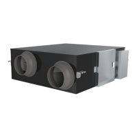
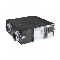
The Gree ERV system is a sophisticated ventilation solution that integrates total heat recovery to manage indoor air quality and energy efficiency. Its primary function is to bring fresh air into a building while simultaneously exhausting stale indoor air. During this process, the system utilizes a total heat recovery device to transfer heat and moisture between the incoming fresh air and the outgoing exhaust air. This heat exchange mechanism helps to pre-condition the incoming fresh air, reducing the energy load on the building's heating and cooling systems. For instance, in winter, heat from the warm exhaust air is transferred to the colder incoming fresh air, reducing the need for the heating system to warm up the air from scratch. Conversely, in summer, heat from the warmer incoming fresh air is transferred to the cooler exhaust air, lessening the burden on the cooling system. This continuous exchange ensures a constant supply of fresh, conditioned air, improving indoor air quality without significant energy penalties. The system also incorporates filters to remove dust particles, fibers, and other impurities from the incoming air before it reaches the heat exchanger, ensuring cleaner air delivery.
Usage Features
The ERV system is designed for use in commercial settings, focusing on comfort and efficiency. It operates within specific environmental conditions: an indoor temperature range of 0~40°C with 20~80% relative humidity, and an outdoor temperature range of -10~48°C with 20~85% relative humidity. Operating outside these parameters may lead to condensate production and potential damage to electrical components. The system is equipped with low-noise centrifugal fans, ensuring quiet operation, which is crucial for maintaining a comfortable indoor environment in commercial buildings.
The installation process is critical for optimal performance. The manual stresses that installation, operation, and maintenance should only be performed by qualified servicemen with specific training. Key installation considerations include ensuring adequate power supply that matches the unit's nameplate specifications, using specialized components for installation to prevent hazards, and ensuring power lines are sufficiently sized. Air ducts and wires must be properly connected to prevent leakage and electrical hazards. The unit should not be exposed to damp, wet, or corrosive environments. Air ducts, dampers, and valves require insulation to prevent condensation. The power cord should not be lengthened by splicing to avoid overheating or fire risks. Air vents must be kept clear of foreign matters, and filters need periodic cleaning to maintain heat transfer efficiency and operational stability. All electrical lines and joints must be secure, and the wired controller should be connected to electricity before use.
Engineering design guidelines are provided to ensure efficient airflow and minimize noise. For instance, each air passage through the ducts should generally not exceed 15 to 30 meters, with internal sectional areas determined by air speed (8m/s for main ducts, 5m/s for branches). Rectangle ducts should have a side proportion not exceeding 4, and all ducts must be nonflammable. The number of bends in each passage should be minimized (not exceeding 3), and bends should be round-arc rather than straight angles to reduce airflow resistance. Duct walls should be smooth, dustless, and pucker-free. To minimize resistance at air vents, indoor rectangular aluminum alloy diffusers or dual-layer grilles (at least 200x200mm) are recommended. For outdoor air vents, a waterproof grille 3 to 4 times the sectional area of the connected duct, with blades facilitating airflow, is suggested. To prevent discharged air from re-entering, a minimum distance of 1000mm should be maintained between two air vents on the outer wall. For noise reduction, installing a muffler inside air passages is recommended, which can reduce sound levels by 4dB to 6dB.
When an electric heater is installed with the ERV, it must be interlocked with the ventilator, meaning the heater only operates when the ventilator is running. Ducts within 800mm of the electric heater and those passing through rooms with fire sources must be made of non-flammable materials. A steel hanger frame, whose type and specification depend on the ERV's weight, must be pre-embedded for stability. Adequate service clearances are necessary for convenient maintenance of the filter and heat exchanger. Outdoor ducts connected to the fresh air inlet and polluted air outlet should be insulated, as should indoor ducts in high temperature and humidity environments within the ceiling. Indoor ducts should also maintain a gradient (1/50~1/30) to prevent water ingress.
Maintenance Features
Routine maintenance is essential for the sustained performance and longevity of the Gree ERV system. The manual outlines several key maintenance activities and checks.
One of the most critical maintenance tasks is the periodic replacement of the filtering element. The air filter must always be installed; otherwise, the heat exchanging core will accumulate dirt and dust, leading to reduced performance. If a noticeable decrease in airflow volume or discharge air volume occurs, it indicates that the filter needs replacement. The replacement period can be displayed via the controller and adjusted based on actual environmental conditions. The process for filter replacement is straightforward: open the access door, remove the old filter, insert the new one, and then close the access door. It is crucial to cut off the power supply before performing any installation or maintenance to prevent electrocution. Wiring arrangements must comply with specified requirements to avoid electrocution or fire.
Before commissioning the unit, a thorough check of the pipeline system is required. This includes verifying the layout of ducts against design drawings, ensuring the firmness of hangers, checking for anticorrosion paint application, and confirming adequate operation space for air filter replacement. The installation location of duct silencers and the overall firmness of the installation must also be verified.
The electric circuit system also requires inspection prior to trial run. This involves checking incoming lines, connection methods, and power voltage against the circuit diagram. All electrical installations must be performed by qualified technicians in accordance with local laws, regulations, and instructions. The power supply must be rated correctly and dedicated to the product, ensuring it is reliable and prevents stress on terminals. Power cords should never be pulled forcibly. Power supply lines must be adequately sized, and any broken lines must be replaced with dedicated ones. Ground wires must be reliably connected to dedicated grounding devices, and the grounding resistance must comply with local regulations. Ground wires should not be connected to tap water pipes, gas pipes, drain pipes, or other unsecured positions. An air switch and leakage switch capable of cutting off the general power supply must be installed. The air switch should incorporate magnetic and hot release functions for short circuit and overload protection. Field wiring must strictly adhere to the circuit diagram provided with the unit.
The manual also provides troubleshooting guidance for common issues. If the airflow volume at the air outlet/inlet decreases significantly, the likely cause is excessive dust accumulation on the air filter, and the recommended action is to replace or clean it. If abnormal sound levels arise at air vents, it suggests a loose air vent installation, requiring re-fixing. If the system fails to start, possible causes include power failure or incorrect power lines, loose transformer terminals on the main board, communication errors (E6), damper or related parts errors (LO), or an unconnected damper control at the main board (LO). Recommended actions for these issues include recovering power supply and checking wiring, reconnecting transformer terminals, checking connections between the controller and main board, inspecting the by-pass damper and its drive, and connecting the damper control.
Gree emphasizes that it is not responsible for adverse results caused by unauthorized modifications to the electric control system by users. Therefore, all maintenance and modifications should be performed by authorized personnel.