EasyManua.ls Logo

Gree FP-34ZD-K User Manual

Gree FP-34ZD-K
15 pages
To Next Page IconTo Next Page
Page #1 background imageLoading...
Page #1 background image
Change for life
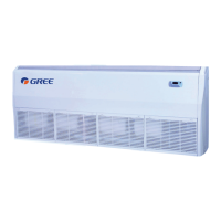
Floor Ceiling Tpye Fan Coil Unit
Commercial or Household Air Conditioners
Owner's Manual(Original lnstructions)
Models:
FP-34WM-D
FP-51WM-D
FP-68WM-D
FP-85WM-D
FP-102WM-D
FP-136WM-D
FP-170WM-D
FP-204WM-D
FP-102WM-K(BMS)
FP-34ZD-K
FP-51ZD-K
FP-68ZD-K
FP-85ZD-K
FP-102ZD-K
FP-136ZD-K
FP-170ZD-K
FP-204ZD-K
FP-136WM-K(BMS)
Thank you for choosing commercial air conditioners.
Please read this Owner’s Manual carefully before operation and retain it for future reference.
If you have lost the Owner's Manual, please contact the local agent or visit www.gree.com
or send an email to global@gree.com.cn for the electronic version.

Other manuals for Gree FP-34ZD-K

Questions and Answers:

Gree FP-34ZD-K Specifications

General IconGeneral
BrandGree
ModelFP-34ZD-K
CategoryHeating System
LanguageEnglish

Summary

User Notice

Intended Use and Installation Locations

Appliance intended for expert/trained users; lists locations causing malfunction.

Product Disposal and Recycling

Guidance on responsible disposal of the product according to EU regulations for environmental protection.

Child Safety and Supervision

Appliance use by children aged 8+, need for supervision, and prohibition of unsupervised cleaning/maintenance.

1 Operation Range

Operational Pressure and Temperature Limits

Details on unit pressure, cooling/heating water temperature, and ambient temperature/humidity ranges.

Application Restrictions

Appliance not suitable for locations with corrosive, inflammable gas, or heavy smog.

2 Notices for operation

User Capability and Supervision

Appliance not for users with impaired capabilities without supervision; children must be supervised.

Electrical Safety Requirements

Damaged cords require professional replacement; fixed wiring needs all-pole disconnection switch.

3 Operating Guide

Filter Cleaning Procedure

Steps for cleaning the air filter using a vacuum or soap water after power is cut.

Unit and Remote Control Cleaning

How to clean the unit and remote control using dry or slightly damp cloth.

Temperature Setting for Energy Efficiency

Set moderate temperature levels to avoid unnecessary energy consumption.

Airflow Direction Adjustment

Adjust louvers and flaps for optimal airflow distribution.

Energy Saving Tips

Close windows/doors, use blinds/curtains, and ensure proper ventilation for energy saving.

Precautions

Electrical Shock and Power Supply Safety

Turn off unit during shock; cut power for long periods; check voltage/frequency and fuses.

Object Insertion and Obstruction Warnings

Do not insert objects into inlets/outlets; avoid placing obstacles around units.

Airflow Exposure and Heat Source Placement

Avoid direct airflow on vulnerable persons; do not place heat sources near the unit.

4 Trouble Shooting

Common Operational Problems and Solutions

Lists common issues like no operation, poor cooling, vapor, and inoperative remote control with causes.

5 Installation

Unit Dimensions and Specifications

Provides a dimensional diagram and a table of model dimensions (A, B, C, D, E, F, G, H) in mm.

Ideal Installation Site Criteria

Requirements for air distribution, drainage, weight support, access, pipe connection, and distance from appliances.

Ventilation and Height Requirements

Ensures adequate space around the unit for ventilation and specifies a minimum installation height from the floor.

Ceiling and Floor Mounting Types

Mentions two installation types: Ceiling and Floor.

Mounting Procedure Steps

Outlines steps for determining position, removing panels, and attaching hanger brackets to suspension bolts.

Hanger Bracket Adjustment and Drainage

Details on securing hanger brackets, adjusting unit height for drainage, and using inward facing brackets.

5.4 Electrical wiring

Power and Valve Wiring Connections

Steps for opening panels, routing cords, connecting wires as per circuit diagram, and reassembling.

Recommended Power Cable Specifications

Recommends 3*0.75mm² cable and specifies suitability for 40°C and 90°C rated cables.

6 Drain Piping Work

Drain Pipe Outlet and Diameter

Specifies drain pipe outlet direction (rear/right) and minimum diameter for connection.

Drain Pipe Installation and Drainage Check

Instructions on inclining pipe, securing hose, insulating clamp, and confirming drainage with water.

7 Motorized valve

Motorized Valve Installation Procedure

Connects tube joint, valve, and outlet tube with torque specifications and thread sealing.

Heat Insulation for Valve Assembly

Recommends wrapping the motorized valve and tube with sponge for heat insulation.

7.2 Electric wiring

Correct Wiring of Water Valve

Details on routing valve wire through pipe sleeve and binding with sponge, avoiding short circuits.

Valve Core Orientation and Sponge Wrapping

Proper orientation of valve core to prevent condensate entry; avoid wrapping entire valve with sponge.

8 Evaluation of the Performance

Performance Checkpoints

Check voltage, measure inlet/outlet temperatures, and verify temperature difference.

Auto-Restart Functionality

The unit has an auto-restart feature to remember the running model after power loss.

9 Check after Installation

Pre-Operation Inspection Checklist

Items to check: firm fixing, insulation, voltage, wiring, earth connection, power cord, and inlet/outlet covers.

10 Test Operation(wireless remoter controller)

Preparation Before Testing

Ensure complete installation, secure wiring, and clear unit of impurities before power-on.

Test Mode Execution and Verification

Steps to enter test mode, select COOL/HEAT/FAN/DRY, and exit test mode.

Related product manuals