Cassette Type FCU
14
replaced by specialized lines.
(5) The unit should be connected to the specialized grounding device by the qualied servicemen. For the
xed lines, there should be the breaker and air switch with sufcient capacity. The air switch should be
of the magnetic or electric trip-off functions so as for shortcutting and overloading protection.
(6) The unit should be grounded reliably. The yellow-green line is the grounding line. Do not put it into
other use, or cut it. The grounding line cannot be xed with self-tapping screws; otherwise it would
lead to electric shock. The grounding line cannot be connected to the running water line, the gas line,
the drain line and where it is not approved.
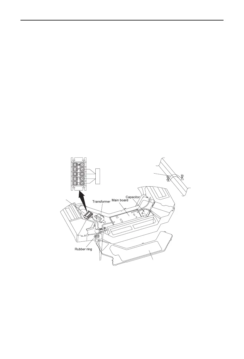
2.9.2 Steps for Electric Wiring
(1) Open the electric box and pull the power lines and connection lines of the electric water valve through
the rubber rings. Then, x them with the wire clamps.
(2) Perform wiring in accordance with the electric wiring diagram.
(3) Fix the lines with the wire clamps.
(4) Connect the control lines.
(5) Pull the control lines through the rubber ring to the wiring terminals.
(6) Wrap the lines with sponge in case of dewing.
(7) Fix the lines and close the electric box cover.
Elements for different models vary, and the gure below is just for reference.
Teminal board
Electric box cover
Wire clamp
Wire clamp
 Loading...