Do you have a question about the Gree GFH(24)EA-K3DNA1A/I and is the answer not in the manual?
Lists available models for outdoor units, BU modules, and indoor units.
Explains the coding system for product model names for various components.
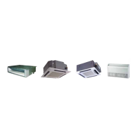
Details the operational functions available for different indoor unit types.
Provides detailed technical specifications for outdoor units, indoor units, and BU modules.
Specifies the operating temperature limits for indoor and outdoor conditions.
Illustrates the refrigerant piping schematic for the Super Free Match multi-system.
Outlines the sequence of operations for the air conditioning system's start-up.
Explains the control functions and operational logic for the outdoor unit.
Details the functions and operation of wired and wireless remote controllers.
Introduces the smart zone controller for regional and centralized system control.
Provides a flowchart outlining the complete installation process for the system.
Covers precautions and procedures for installing the outdoor unit and its space.
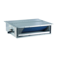
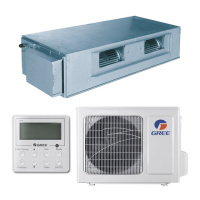
Details the installation process for various indoor unit types.
Explains the installation location and procedures for the BU module.
Covers refrigerant piping installation, including length, diameter, and oil traps.
Details electrical wiring requirements and precautions for the entire system.
Provides guidelines for installing the condensate drainage pipeline correctly.
Introduces the testing board for detecting unit status, running functions, and errors.
Offers guidance on diagnosing and resolving common unit malfunctions.
Presents flowcharts for troubleshooting specific error displays and conditions.
Shows diagrams of the system's power distribution and wiring.
Lists resistance values for temperature sensors at various temperatures for diagnostics.
Provides step-by-step guides for disassembling and assembling major components.
Offers exploded views and part lists for identifying and ordering components.
| Brand | Gree |
|---|---|
| Model | GFH(24)EA-K3DNA1A/I |
| Category | Air Conditioner |
| Language | English |