U-Match Series DC Inverter Service Manual
111
High pressure switch for fan speed
adjustment
Pressure protection switch for fan speed
adjustment
High pressure switch for
systemprotection(obligate)
Interface of high pressure protection
Low pressure switch for system
protection (obligate)
Interface of low pressure protection
Compressor overload protection
Interface of compressor overload protection
1&2 pin: Tube sensor
3&4 pin: Ambient temperature
5&6 pin: Air discharge
1&2 pin: Case temperature sensor
3&4 pin: Ambient temperature sensor
5&6 pin: Discharge temperature sensor
Electronic expansion valve line
1 to 4-pin: Drive impulse output;5-pin:
+12V;
Interface of electronic expansion valve:
1 to 4-pin: Drive impulse output;
5-pin: +12V;
Compressor electrical heater
Compressor electric heating belt
Chassis electrical heater
Chassis electric heating belt
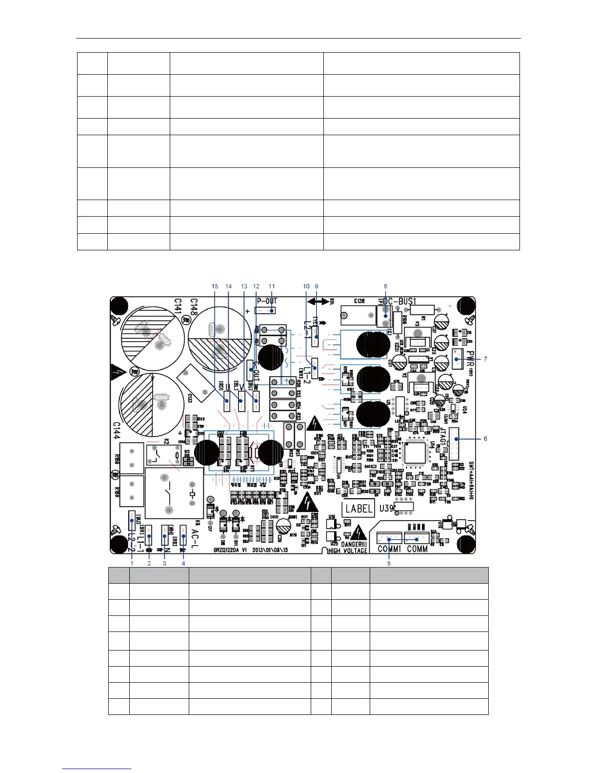
GUHD18NK3FO/GUHD24NK3FO/ GUHD30NK3FO/ GUHD36NK3FO/ GUHD42NK3FO
(1) Driving Board
PFC induction wire (blue)
PFC induction wire (brown)
Neutral wire input (white)
Bus electric discharging
interface (for testing)
PFC induction wire (yellow)
PFC induction wire (white)
 Loading...