DC Inverter Multi VRF System
18
4.3.7 Thermal Insulation for Pipeline
(1) For multi VRF system, every copper pipe should be labeled so as to avoid
misconnection.
(2) At the branch inlet, leave at least 500mm straight pipe section.
(3) Thermal insulation for pipeline
1) To avoid condensate or water leakage on the connection pipe, the gas pipe and liquid
pipe must be wrapped with thermal insulating material and adhesive tape for insulation
from the air.
2) Thermal insulating material shall be able bear the pipe temperature. For heat pump
unit, liquid pipe should bear 70℃ or above and gas pipe should bear 120℃ or above.
For cooling only unit, both liquid pipe and gas pipe should bear 70℃ or above.
3) Example: Polyethylene foam (bear 120℃ or above); foaming polyethylene (bear 100℃
or above)
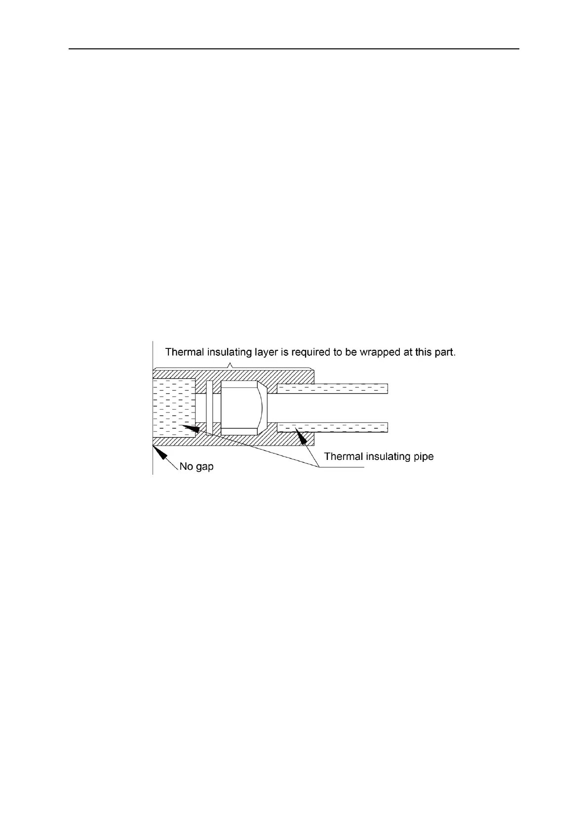
4) Joints of indoor and outdoor unit should be wrapped with insulating material and leave
no gap between pipe and wall. See Fig.18.
Fig.25
5) Thermal insulating material of branches should be the same as that of the pipeline. The
attached foam of branches cannot be taken as insulating material.
6) When wrapping the tape, the later circle should cover half of the former one. Don’t
wrap the rape too tight, otherwise the insulation effect will be weakened.
7) After wrapping the pipe, apply sealing material to completely seal the hole on the wall.
4.3.8 Support and Protection of Pipeline
(1) Support should be made for hanging connection pipe. Distance between each support
cannot be over 1m.
(2) Protection against accidental damage should be made for outdoor pipeline. When
pipeline exceeds 1m, a pinch board should be added for protection.
Copyright 2018. This translation is property of GREE PRODUCTS SL. All rights reserved. Total or partial reproduction without its express authorization is prohibited.
 Loading...