GMV DC Inverter VRF
45
When two wired controllers control multiple IDUs, the wired controller can be connected to
any one IDU, provided that the connected IDU is of the same series. Meanwhile, one and only
one of the wired controllers must be set as a slave controller. At most 16 IDUs can be
controlled by wired controllers and the connected IDUs shall be within a same IDU network.
No matter when unit is turned on or off, slave controller can be set.
How to set a slave controller: hold “function” button on the designated controller for 5s, and
temperature zone displays C00. Continue holding “function” button for 5s and setting screen of
controller parameter will come out. Default temperature zone displays P00.
Press button o button to select parameter code P13. Press “mode” button to switch to
setup of parameter values. Then the parameter value will blink. Press button or button to
select code 02. And then press “confirm/cancel” to finish setting.
Press “confirm/cancel” to return to the previous display until you exit from the setup of
parameter values.
Below are user’s parameter settings:
Set up
address for
wired
controller
01: master wired
controller
02: slave wired
controller
When 2 wired controllers control one or more
IDUs, they shall have different addresses.
Slave wired controller (02) can’t set up units’
parameters except its own address.
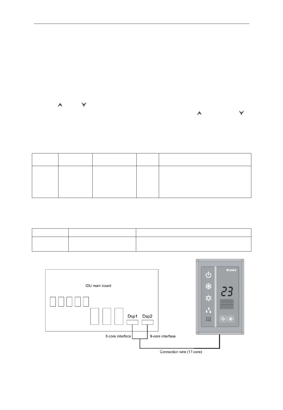
4.7.3 Communication connection between duct type IDU and light board receiver
When the duct type IDU needs to be connected to light board remote receiver, it can be
connected via Dsp1 and Dsp2 on the IDU main board.
Main board interface of corresponding IDU
Dsp1 (direct to 8-core interface)
Dsp2 (direct to 9-core interface)
Fig. 4.7.7
 Loading...