EasyManuals Logo

Gree GMV-450WM/B-X User Manual

Gree GMV-450WM/B-X
68 pages
To Next Page IconTo Next Page
To Previous Page IconTo Previous Page
Page #28 background imageLoading...
Page #28 background image
D.C. Inverter Multi VRF Modular
25
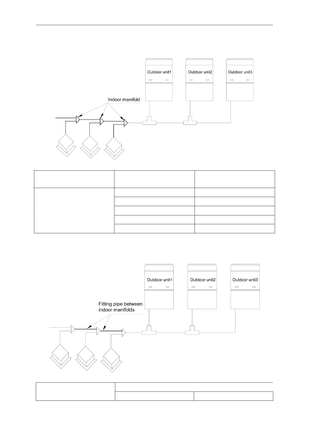
4.2.5.5 Manifold at indoor unit side
Manifold at indoor unit side can be selected as per total capacity of downstream indoor unit(s).
Refer to the following table.
Fig.28
R410A Refrigerant System
Total capacity of downstream indoor
unit(s) C (kW)
Model
Y-type Manifold
C20.0
FQ01A/A
20.0
C30.0
FQ01B/A
30.0
C70.0
FQ02/A
70.0
C135.0
FQ03/A
135.0
C
FQ04/A
4.2.5.6 Fitting pipe between manifolds
Pipe size (between two manifolds at indoor unit side) is based on the total capacity of
upstream indoor unit(s).
Fig.29
Total capacity of downstream indoor
unit(s) C(kW)
Dimension of the pipe of indoor branch
Gas Pipe(mm)
Liquid Pipe (mm)

Other manuals for Gree GMV-450WM/B-X

Questions and Answers:

Question and Answer IconNeed help?

Do you have a question about the Gree GMV-450WM/B-X and is the answer not in the manual?

Gree GMV-450WM/B-X Specifications

General IconGeneral
BrandGree
ModelGMV-450WM/B-X
CategoryAir Conditioner
LanguageEnglish

Related product manuals