GMV Heat Recovery DC Inverter VRF
57
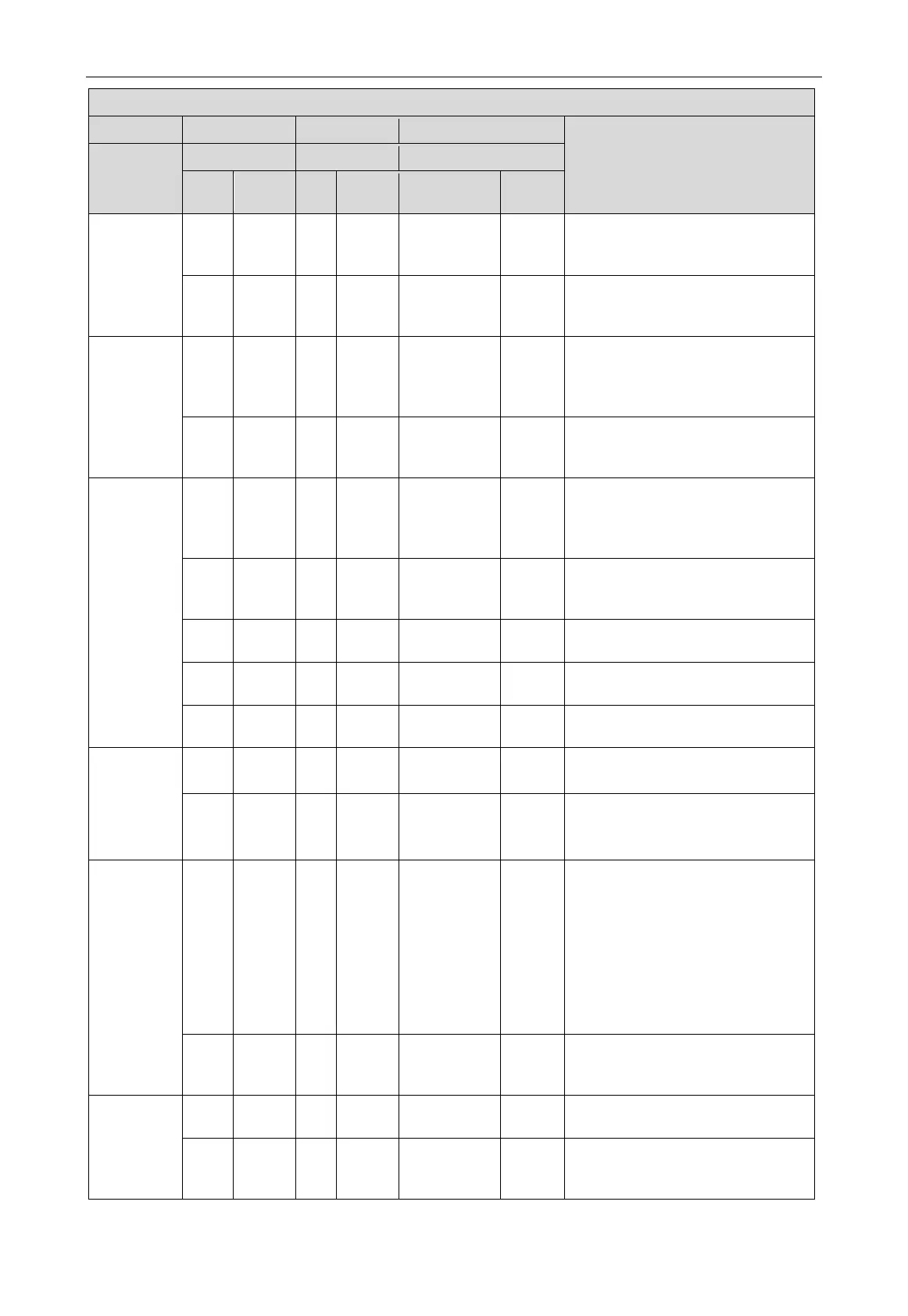
Instruction for each stage progress at the time of debugging
—
Meaning
Progress
Code
Display
Code
Display
Code
Display
03_module
quantity
confirmation
db ON 03 ON 01~04 Flash
LED3 displays the module quantity. It
needs to manually confirm the module
db ON 03 ON OC ON
Once the system module quantity is
confirmed, it will automatically enter
into the next step for judgment.
04_indoor
unit quantity
confirmation
db ON 04 ON
××
/ The
quantity of
online indoor
Flash
LED3 displays the quantity of online
indoor units.
db ON 04 ON OC ON
Indoor unit’s quantity inspection is
finished. Enter into the next step
05_ detect
internal
communication
db ON 05 ON C2 ON
The system has detected
“
communication malfunction between
main control and inverter compressor
”
db ON 05 ON C3 ON
The system has detected
“
communication malfunction between
main control and inverter fan driver
”
db ON 05 ON CH ON
“
rated capacity
ratio is too high.
”
db ON 05 ON CL ON
“
rated capacity
ratio is too low
”
db ON 05 ON OC ON
System inspection is finished. Enter
into the next step automatically.
06_outdoor
unit
components
inspection
db ON 06 ON
corresponding
ON
The system has detected the fault of
outdoor unit’ components.
db ON 06 ON OC ON
The system detected that there’s no
outdoor unit fault. Enter into the next
step automatically.
07_indoor
unit
components
inspection
db ON 07 ON
XXXX/
corresponding
error code
ON
The system detected an indoor unit
fault. XXXX indicates engineering
number of fault indoor unit, and the
corresponding fault code is displayed
2s later. For example, if there is D5
fault in the No. 100 indoor unit, LED3
displays as follows: 01 (after 2s) 00
(after 2s) d5, and they will be displayed
circularly.
db ON 07 ON OC ON
The system detected that there’s no
outdoor unit fault. Enter into the next
08_compress
or preheat
confirmation
db ON 08 ON U0 ON
Preheat time for compressor is
db ON 08 ON OC ON
Preheat time for compressor is
enough. Enter into the next step
 Loading...


