Air-to-water Heat Pump
71
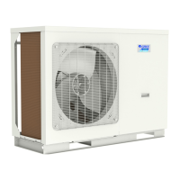
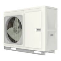
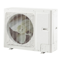
MONOBLOC
TYPE
Note: rstly please cut o the power supply and discharge refrigerant out of the unit.
Operation Procedure Illustration
GRS-CQ8.0Pd/NhG3-E, GRS-CQ10Pd/NhG3-E, GRS-CQ12Pd/NhG3-E, GRS-CQ14Pd/NhG3-E, GRS-CQ16Pd/NhG3-E
GRS-CQ8.0Pd/NhG4-E, GRS-CQ10Pd/NhG4-E, GRS-CQ12Pd/NhG4-E, GRS-CQ14Pd/NhG4-E, GRS-CQ16Pd/NhG4-E
GRS-CQ8.0Pd/NhG3-M, GRS-CQ10Pd/NhG3-M, GRS-CQ12Pd/NhG3-M, GRS-CQ14Pd/NhG3-M, GRS-CQ16Pd/NhG3-M
GRS-CQ8.0Pd/NhG4-M, GRS-CQ10Pd/NhG4-M, GRS-CQ12Pd/NhG4-M, GRS-CQ14Pd/NhG4-M, GRS-CQ16Pd/NhG4-M
Remove the cover of both the electic box and the
inductance box.
Remove the electric box and the inductance box.
Remove fastening bolts, desolder the joints between
the plate heat exchanger gas/liquid pipe and the
refrigerant system, and then remove the water system.
(when desoldering the connection joint, pay attention
to covering the solder joints with a damp cloth to avoid
high temperature damage).
Remove the 4-way valve.
• Loosen the screws xing the coil of 4-way valve
• Remove the coil of 4-way valve
• Unsolder the tubes connected to the 4-way valve.
• Remove the 4-way valve.
• Note:when desoldering the connection joint, pay
attention to covering the solder joints with a damp cloth
to avoid high temperature damage.
 Loading...