Air-to-water Heat Pump
72
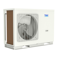
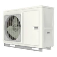
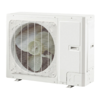
MONOBLOC
TYPE
Note: rstly please cut o the power supply and discharge refrigerant out of the unit.
Operation Procedure Illustration
GRS-CQ8.0Pd/NhG3-E, GRS-CQ10Pd/NhG3-E, GRS-CQ12Pd/NhG3-E, GRS-CQ14Pd/NhG3-E, GRS-CQ16Pd/NhG3-E
GRS-CQ8.0Pd/NhG4-E, GRS-CQ10Pd/NhG4-E, GRS-CQ12Pd/NhG4-E, GRS-CQ14Pd/NhG4-E, GRS-CQ16Pd/NhG4-E
GRS-CQ8.0Pd/NhG3-M, GRS-CQ10Pd/NhG3-M, GRS-CQ12Pd/NhG3-M, GRS-CQ14Pd/NhG3-M, GRS-CQ16Pd/NhG3-M
GRS-CQ8.0Pd/NhG4-M, GRS-CQ10Pd/NhG4-M, GRS-CQ12Pd/NhG4-M, GRS-CQ14Pd/NhG4-M, GRS-CQ16Pd/NhG4-M
Remove the suction line
• Loosen the bolts xing the gas valve.
• desolder the line connected to the gas valve.
• Note:when desoldering the connection joint, pay
attention to covering the solder joints with a wet cloth
to avoid high temperature damage.
Remove the economizer
• Loosen the bolts xing the .
• Unsolder the pipe connected to the liquid valve.
• Note:when desoldering the connection joint, pay
attention to covering the solder joints with a damp cloth
to avoid high temperature damage.
Remove compressor and gas-liquid separator
• Remove the connection wire of compressor.
• Unsolder the suction pipe and discharge pipe.
• Loosen the bolts xing the compressor and remove the
compressor and gas-liquid separator.
Remove the ting bolts and the fan.
 Loading...