GREE U-Match 5 SERIES UNIT SERVICE MANUAL
75
4. Maintenance
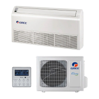
4.1 System Diagram
4.2 Connection Pipe Vacuum Pumping
Make sure the outlet of vacuum pump is away from fire source and is well-ventilated.
(1)Remove the caps of the liquid valve, gas valve and also the service port.
(2)Connect the hose at the low pressure side of the manifold valve assembly to the service port of the unit‘s gas valve, and
meanwhile the gas and liquid valves should be kept closed in case of refrigerant leak.
(3)Connect the hose used for evacuation to the vacuum pump.
(4)Open the switch at the lower pressure side of the manifold valve assembly and start the vacuum pump. Meanwhile, the switch
at the high pressure side of the manifold valve assembly should be kept closed, otherwise evacuation would fail.
(5)The evacuation duration depends on the unit‘s capacity, generally.
GUD71W/NhA-T, GUD85W/NhA-T, GUD100W/NhA-T,
GUD100W/NhA-X
GUD125W/NhA-T, GUD140W/NhA-T, GUD125W/NhA-X,
GUD140W/NhA-X, GUD160W/NhA-X
And verify if the pressure gauge at the low pressure side of the manifold valve assembly reads -1.0Mp (-75cmHg), if not, it indicates
there is leak somewhere. Then, close the switch fully and then stop the vacuum pump.
 Loading...