10
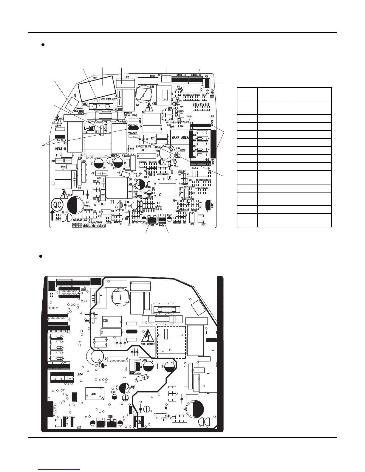
Schematic Diagram
BOTTOM VIEW
TOP VIEW
For 18K Unit
1
2
345 6 7
8
9
10
11
1213
14
1
Power supply live wire
connector
2
Power supply neutral wire
connector
3 Protective tube
4 Fan capacitor
5 PG motor connector
6 Auto button
7 Up & down swing connector
8 PG motor fan feedback terminal
9 Display panel connector
10
Indoor and outdoor unit
communication wire terminal
11 Jumper cap terminal
12
Indoor ambient temperature
sensor
13 Indoor pipe temperature sensor
14
Health function
terminal(optional)
 Loading...