19
Technical Information
Service Manual
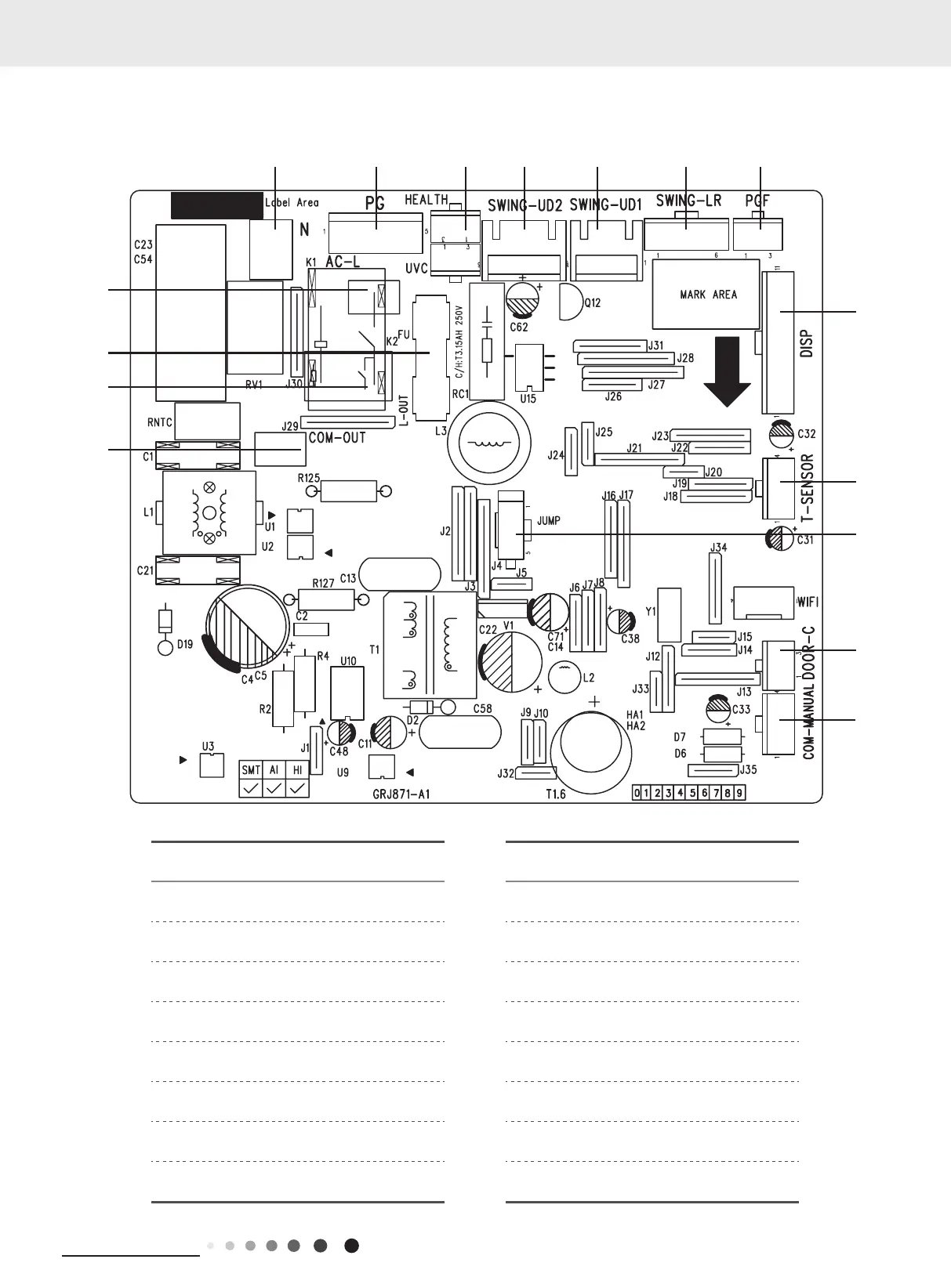
5.2 PCB Printed Diagram
Indoor Unit
No. Name No. Name
1 Terminal of communication 9
Left &Right swing interface(only for the
model with this function)
2 Fuse 10 Interface of PG feedback
3 Live wire terminal 11 Display interface
4 Neutral wire terminal 12 Terminal of temperature sensor
5 PG Motor terminal 13 Jumper cap
6 Interface of health function 14
Interface of gate-control (only for the
model with this function)
7 Up&down swing interface 2 15
Wired controller terminal (only for the
model with this function)
8 Up&down swing interface 1 16
Terminal of live wire used for supplying
power for outdoor unit
5. Electrical Part
3
16
2
1
11
12
13
14
15
7K
 Loading...