Do you have a question about the Gree GWH09QB-K3DNA1B and is the answer not in the manual?
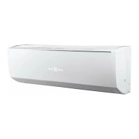
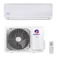
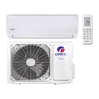
Overview of product models including indoor and outdoor units.
Technical specifications for capacity, power, and dimensions.
Illustrates operation curves and capacity variation with temperature.
Detailed dimension diagrams and measurements for the indoor unit.
Dimension diagrams and measurements for the outdoor unit.
Illustrates refrigerant flow for cooling and heating modes.
Shows wiring connections for indoor and outdoor units.
Displays printed circuit board layouts for indoor and outdoor units.
Introduces remote controller buttons, display icons, and basic operation.
Explains basic system modes and other control features.
Essential safety guidelines and warnings for installation and maintenance.
Safety measures specific to the installation process.
Guidelines for selecting installation location and preparation.
Steps for mounting units, connecting pipes, and drain hoses.
Requirements and connections for the unit's electrical system.
Guides on vacuum pumping, leak detection, and test operations.
Lists error codes, their meanings, and possible causes for troubleshooting.
Provides detailed troubleshooting guides for common malfunctions.
Exploded views and part lists for the indoor unit.
Exploded views and part lists for the outdoor unit.
Detailed steps for removing indoor unit components.
Step-by-step instructions for disassembling the outdoor unit.
Provides conversion tables between Celsius and Fahrenheit.
Details specifications for connecting pipes and refrigerant charge.
Provides a guide on the correct method for pipe expanding.
Lists resistance values for temperature sensors at various temperatures.
| Energy Efficiency Ratio (EER) | 3.21 |
|---|---|
| COP | 3.61 |
| Power Supply | 220-240V, 50Hz |
| Refrigerant | R410A |
| Weight (Indoor Unit) | 9 kg |
| Type | Split System |
| Outdoor Unit Noise Level | 52 dB(A) |
| Cooling Capacity | 2.6 kW |