Do you have a question about the Gree GWH09QB-K3DNA2B and is the answer not in the manual?
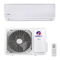
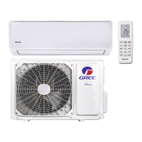
Provides an overview of the GREE air conditioning models covered in the manual.
Details technical specifications for indoor and outdoor units, including electrical and performance data.
Presents dimensional drawings of the indoor and outdoor units for installation planning.
Illustrates the refrigerant circuit for both cooling and heating modes.
Contains wiring diagrams and PCB layout information for the unit's electrical components.
Explains the various operating modes, functions, and remote controller usage.
Important safety precautions and general guidelines for proper installation and maintenance.
Step-by-step instructions and considerations for installing the air conditioning unit.
Covers error code lists, troubleshooting procedures, and general maintenance tasks.
Visual breakdown of unit components with associated part numbers for identification.
Detailed instructions on how to disassemble and remove components of indoor and outdoor units.
Provides conversion tables for temperature readings between Celsius and Fahrenheit.
Specifies requirements for refrigerant pipe length and diameter based on cooling capacity.
Details the correct procedure for expanding refrigerant pipes to prevent leaks.
Lists resistance values for temperature sensors at different ambient temperatures.
| Brand | Gree |
|---|---|
| Model | GWH09QB-K3DNA2B |
| Category | Air Conditioner |
| Language | English |