Do you have a question about the Gree GWH12AAB-K3NNA1A and is the answer not in the manual?
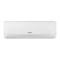
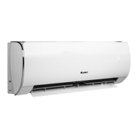
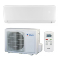
Overview of the air conditioner models and their components.
Detailed technical specifications for various models of the air conditioner.
Comprehensive table of electrical and mechanical specifications for each model.
Graphs illustrating cooling and heating capacity ratios at varying outdoor temperatures.
Tables detailing cooling and heating performance under rated frequency conditions.
Diagrams showing the physical dimensions of indoor and outdoor units.
Dimensional drawings and measurements for the indoor air conditioning unit.
Dimensional drawings and measurements for the outdoor air conditioning unit.
Schematic illustrating the refrigerant flow and components in the cooling and heating model.
Information regarding the electrical systems, including wiring and PCB diagrams.
Diagrams showing the electrical connections and wiring for the unit.
Visual layout of the Printed Circuit Board (PCB) with component identification.
Details on the functions and controls of the air conditioner, including remote operation.
Explanation of the buttons and icons on the YAW1F remote controller.
Explanation of the buttons and icons on the YAW1F1 remote controller.
Overview of various operating modes, functions, and error codes.
Details on additional control functions like timer, sleep, turbo, and swing.
Information on special functions such as health and 'I Feel' modes.
Important safety precautions and guidelines for installation and maintenance procedures.
Step-by-step guide for the proper installation of the air conditioning unit.
Diagrams specifying clearance requirements for indoor and outdoor unit installation.
List of parts to check before commencing the installation process.
Recommendations and considerations for choosing the optimal installation location.
Guidelines for safe and correct electrical connections and wiring.
Detailed instructions for installing the indoor unit, including mounting.
Detailed instructions for installing the outdoor unit, including support and fixing.
Procedures for vacuum pumping and detecting refrigerant leaks in the system.
Steps for checking the installation and performing test operations.
Procedures and information related to the maintenance of the air conditioner.
Table listing error codes, their display methods, status, and possible causes.
Flowcharts and steps to diagnose and resolve common malfunctions.
Methods for addressing common issues like unit not starting or poor cooling/heating.
Conversion tables for temperature readings between Celsius and Fahrenheit scales.
Guidelines and specifications for connection pipe length and refrigerant charging.
Step-by-step instructions for properly expanding pipe ports for installation.
Resistance values for temperature sensors at various ambient and tube temperatures.
| Cooling Capacity | 12000 BTU/h |
|---|---|
| Energy Efficiency Ratio (EER) | 3.21 |
| Power Supply | 220-240V, 50Hz |
| Refrigerant | R32 |
| Weight (Indoor Unit) | 8.5 kg |
| Operating Temperature (Heating) | -7-24°C |
| Type | Split Air Conditioner |
| Noise Level (Outdoor) | 52 dB(A) |
| Operating Temperature (Cooling) | 18°C to 43°C |