41
Technical Information
Service Manual
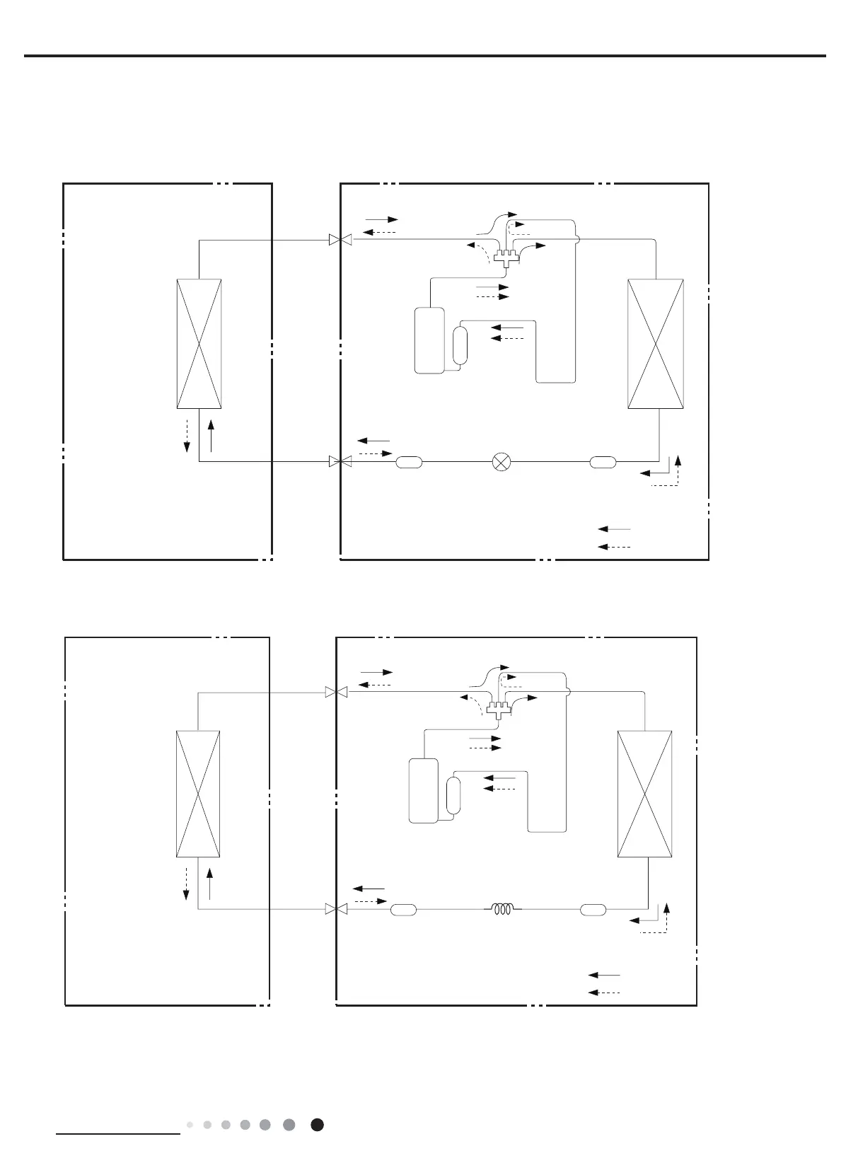
4. Refrigerant System Diagram
Connection pipe specication:
Liquid pipe:1/4"
Gas pipe:3/8" (09/12K)
Gas pipe:1/2" (18K)
Gas pipe:5/8" (24K)
COOLING
HEATING
4-Way valve
Discharge
Suction
Heat
exchanger
(evaporator)
Heat
exchanger
(condenser)
Valve
Valve
Liquid pipe
side
Gas pipe
side
Strainer Electric
expand
valve
Strainer
Compressor
Accumlator
COOLING
HEATING
4-Way valve
Discharge
Suction
Heat
exchanger
(evaporator)
Heat
exchanger
(condenser)
Valve
Valve
Liquid pipe
side
Gas pipe
side
Strainer
Strainer
Capillary
Accumlator
Compressor
Cooling and heating model
All models except:GWH09QB-K6DNA1E/O GWH18YD-K6DNA1A/O GWH24YE-K6DNA1A/O
GWH09AGA-K6DNA1A/O GWH12AGB-K6DNA1A/O
Cooling and heating model
GWH09QB-K6DNA1E/O GWH09AGA-K6DNA1A/O GWH12AGB-K6DNA1A/O
 Loading...