Do you have a question about the Gree GWH18KG-K3DNB1G and is the answer not in the manual?
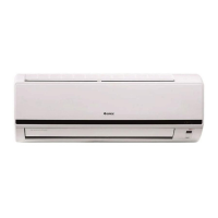
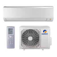
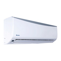
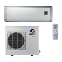
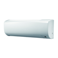
Overview of indoor unit models and their corresponding images.
Detailed technical specifications for indoor and outdoor units.
Data sheet for cooling and heating performance under rated conditions.
Graphs illustrating noise levels for indoor and outdoor units.
Diagrams showing the dimensions of indoor and outdoor units.
Detailed dimensional drawings of the indoor unit.
Detailed dimensional drawings of the outdoor unit.
Schematic representation of the refrigerant circuit within the air conditioner.
Details on the electrical components and wiring diagrams.
Wiring diagrams for the indoor unit.
Visual representation of the Printed Circuit Board layout for indoor and outdoor units.
Explanation of remote controller functions and display icons.
Explanation of remote controller buttons and display screen icons.
Detailed explanation of operating modes and functions of the air conditioner.
Important safety precautions and general notes for installation and maintenance.
Essential safety guidelines to follow before starting installation.
Crucial safety measures related to electrical work during installation.
Safety guidelines for handling refrigerants during installation.
List and images of essential tools required for installation and maintenance.
Procedures and guidelines for installing the air conditioning unit.
Visual guide for recommended clearance dimensions during installation.
A flowchart outlining the overall installation process steps.
Checklist for verifying all necessary installation parts are present.
Criteria and recommendations for choosing suitable installation locations.
Guidelines and safety precautions for electrical connections.
Step-by-step instructions for installing the indoor unit.
Step-by-step instructions for installing the outdoor unit.
Procedures for evacuating the system and checking for refrigerant leaks.
Final checks and operational tests after installation is complete.
Information on malfunction display and troubleshooting for indoor units.
Information on how indoor unit malfunctions are displayed and error codes.
Step-by-step troubleshooting guides for various indoor unit malfunctions.
Common issues and their troubleshooting steps, categorized by problem.
Visual breakdown of components and their part numbers for assembly/disassembly.
Exploded view and part list for the indoor unit with corresponding part codes.
Exploded view and part list for the outdoor unit with corresponding part codes.
Step-by-step instructions for safely removing unit components.
Step-by-step instructions for disassembling the indoor unit.
Step-by-step instructions for disassembling the outdoor unit.
Conversion table for temperature readings between Celsius and Fahrenheit.
Guidelines on connection pipe lengths and refrigerant charging amounts.
Detailed steps for properly expanding refrigerant pipes to prevent leaks.
Tables showing resistance values for temperature sensors at different temperatures.
| Cooling Capacity | 18000 BTU/h |
|---|---|
| Heating Capacity | 18000 BTU/h |
| Power Supply | 220-240V/50Hz |
| Refrigerant | R410A |
| Indoor Unit Dimensions (W x H x D) | 1000 x 300 x 210 mm |
| Outdoor Unit Dimensions (W x H x D) | 800 x 600 x 300 mm |
| Weight (Outdoor Unit) | 38 kg |
| Noise Level (Outdoor Unit) | 54 dB(A) |
| Dehumidification Capacity | 1.8 L/h |
| Type | Split System |
| Operating Temperature (Cooling) | 18°C to 43°C |
| Indoor Unit Weight | 13.5 kg |