Do you have a question about the Gree GWH18KG-K3DNA6G and is the answer not in the manual?
| Brand | Gree |
|---|---|
| Model | GWH18KG-K3DNA6G |
| Category | Air Conditioner |
| Language | English |
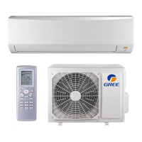
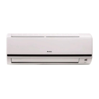
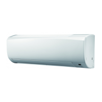
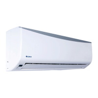
Provides a brief overview of the air conditioner models and their components.
Details technical specifications for the indoor and outdoor units.
Presents a detailed table of technical specifications for the units.
Shows performance curves related to compressor speed and temperature.
Illustrates how capacity changes with ambient temperature.
Provides data sheets for cooling and heating at rated frequency.
Displays noise level curves for indoor and outdoor units.
Presents dimensional drawings of the indoor and outdoor units.
Shows the dimensions and mounting details of the indoor unit.
Displays the dimensions and mounting details of the outdoor unit.
Illustrates the refrigerant flow and key components of the system.
Covers electrical diagrams and PCB layouts for the unit.
Provides wiring diagrams for the indoor and outdoor units.
Shows the printed circuit board layouts for indoor and outdoor units.
Explains the operational modes and functions of the air conditioner.
Introduces the buttons and icons on the remote controller.
Describes the basic functions and operational modes of the unit.
Outlines important safety precautions and guidelines for installation and maintenance.
Provides detailed procedures and requirements for installing the air conditioner.
Illustrates the required clearances and spatial dimensions for installation.
Lists the parts to check before and during installation.
Guides on choosing the optimal location for indoor and outdoor units.
Details electrical safety precautions and connection requirements.
Step-by-step guide for installing the indoor unit.
Step-by-step guide for installing the outdoor unit.
Explains the process of vacuum pumping and detecting refrigerant leaks.
Outlines checks and test operations after installation.
Details procedures for maintaining the unit, including malfunction displays and troubleshooting.
Describes how malfunctions are displayed on the indoor unit.
Provides diagnostic flowcharts for common malfunctions.
Lists common issues and their troubleshooting steps.
Shows exploded diagrams and lists of parts for indoor and outdoor units.
Provides an exploded view and parts list for the indoor unit.
Provides an exploded view and parts list for the outdoor unit.
Describes the step-by-step process for removing indoor and outdoor unit components.
Details the steps for disassembling the indoor unit.
Details the steps for disassembling the outdoor unit.
Provides conversion tables between Celsius and Fahrenheit temperatures.
Details specifications and requirements for connection pipes, including length and refrigerant charging.
Explains the correct procedure for expanding refrigerant pipes to prevent leaks.
Lists resistance values for temperature sensors at various temperatures.